background image

G2

 Operators Manual 


         Page 7 

Front Panel Familiarisation 


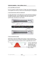
Level Meter: 

this meter displays the 

instantaneous available headroom available at 

the input, just after the analogue to digital 

converter. 

Active Key:  

Switches the entire channel 

on/off – LED illuminated when processing is 
active.  Note that the Listen mode may still be 

active when the channel is bypassed. 

Threshold Control:  

Set the threshold at which the gate will open, from -40dBu to 

+22dBu (effectively off). 

Threshold Meter:  

This meter display the closeness to the threshold, ranging itself 

dependant on the setting of the Threshold control and the input level.  The yellow 
LED shows the point at which the gate will open. 


Attack Control:  

Set how fast the gate will 

open (the fade-in time) – the ‘60uS’ setting uses 
look ahead delay to open the gate before the 

main signal arrives, so preserving the entire 

waveform. 

Hold Control:  

Set how long the gate stays fully 

open after the signal has dropped below the 

threshold, and before entering the release phase.   

Release Control:  

Once the signal has dropped below the threshold and the hold 

time has expired, this control determines how quickly it is attenuated (the fade-out 

time). 

Gate and Gain Reduction Metering:  

The large green LED is only ever illuminated 

when there is less than 6dB of attenuation on the channel (so effectively the gate is 

fully ‘open’).  As the attenuation increases, this LED goes off, and the red meter 
begins to illuminate right to left.  This shows increasing gain reduction, until the final 

large red LED illuminates when there is more than 40dB of attenuation. 


Range/Ratio Control:  

In Gate mode, this control sets the 

maximum attenuation allowed (the Range) when the gate is fully 

closed.  Note that if the Range is set to less 40dB, the large RED 

led may never illuminate.  In Expand mode, this control 
determines the degree of attenuation as the signal drops below 

the threshold. 

MODE


Key:  

Switch the channel between Gate mode and 

Expand mode.  HOLD this key to change modes.  Note that the 

control markings for Gate mode range are boxed. 

Summary of Contents for G2

Page 1: ......

Page 2: ...of the unit just after the analogue to digital converter stage As the unit is unable to add any gain to the signal there is no need for an output meter ü When in Expander mode the Hold knob has no effect ü Remember that you won t hear the effect of the parametric sidechain band unless there is cut or boost applied use the GAIN switch to cycle through the levels ü The Listen LED always flashes when...

Page 3: ... the Hold Time 13 Expanders and Expansion the subtler approach 15 What does an Expander do 15 Why are Expanders necessary 15 How does a Expander work 16 What is the difference between an Expander and a Noise Gate 18 Sidechain Equalisation How and When to Use it 19 When would Sidechain EQ be useful 19 How would sidechain EQ normally be implemented 19 Picking out instruments for gating 19 Look Ahead...

Page 4: ...DE CHOC ELECTRIQUE NE PAS ENLEVER NE PAS EXPOSER A LA PLUIE NI A L HUMITE It should not be necessary to remove any protective earth or signal cable shield connections Do not defeat the purpose of the polarized or grounding type plug A polarized plug has two blades with one wider than the other A grounding type plug has two blades and a third grounding prong The wider blade and the third prong are ...

Page 5: ...ned and engineered for cutting edge performance and world class reliability If you would like further information about this or any other XTA product please contact us We look forward to hearing from you in the near future Unpacking the G2 After unpacking the unit please check it carefully for any damage If any is found immediately notify the carrier concerned you the consignee must instigate any ...

Page 6: ...atures Look ahead attack for true clickless operation and instantaneous opening of the gate Fully adjustable envelope controls including hold time in Gate mode with large easy to see metering Sidechain EQ built in including low and high pass filters and an additional parametric section with variable stepped gain and high resolution frequency adjustment Expander mode for more subtle gating applicat...

Page 7: ...r the signal has dropped below the threshold and before entering the release phase Release Control Once the signal has dropped below the threshold and the hold time has expired this control determines how quickly it is attenuated the fade out time Gate and Gain Reduction Metering The large green LED is only ever illuminated when there is less than 6dB of attenuation on the channel so effectively t...

Page 8: ...ow frequency content out of the sidechain signal up to 5kHz Low Pass Frequency Control Cut high frequency content out of the sidechain signal down to 250Hz LISTEN Key Switches the output of the sidechain filter into the main signal path so that the required range of frequencies may be more easily selected LED flashes as a reminder that this is selected HOLD to engage this function STEREO Key Enabl...

Page 9: ... proof holder adjacent to the mains inlet A spare fuse is also located in this holder Mains Inlet connected via a standard IEC socket Audio In Out 3 pin XLR sockets are provided for each channel All are fully balanced pin 2 hot 3 cold 1 screen Always replace the fuse with the correct type and rating as shown on the rear panel legend ...

Page 10: ...front panel alerts the user to the fact that several keys require a press and hold action to initiate them These keys relate to functions that could accidentally introduce large changes of level at the outputs causing undesirable effects and possible damage These keys have their function marked in BOLD and a different font to make it clear that they will only change state if the key is held in for...

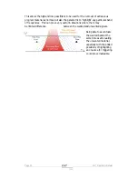
Page 11: ...gnal from a bass drum microphone a burst of signal but perhaps with unwanted pickup from lighting dimmers producing a background buzz Setting the threshold just above the level of the buzz would keep the gate closed during periods were the bass drum was not being played only allowing signal through when the output would be sufficient to mask the noise anyway The output graph above highlights sever...

Page 12: ...change will make it sound like a click Changing the distance between the gate being closed and open will remove this click but also defeat the purpose of the gate in the first place if the range is set high enough to prevent the click it s probably not gating the signal enough anyway As mentioned earlier if the attack is set too slow the gate will not open in time and part of the signal will be lo...

Page 13: ...et the range at maximum and leave it When the gate is fully closed no signal will be heard when the range is set like this In some situations this much attenuation can sound quite unnatural especially if the threshold is set high to gate a loud signal due to the stark contrast between the gate fully closed and fully open It s also worth remembering that if the background noise is quite severe remo...

Page 14: ...th tricky situations where the gate might open and close erratically such as when there is a lot of background noise This problem coupled with a long release can cause sporadic bursts of noise to open the gate in situations when it would be better to hold it open slightly longer ...

Page 15: ...this level should be the same for all devices This is definitely not the case Certainly when the majority of instruments and devices are turned off assuming they are powered in some way they will all share a similar minimum output level However once on it is the noise floor of the electronics within that determines the minimum output A signal that is below the noise floor of any piece of equipment...

Page 16: ...ed How does a Expander work Consider again the signal burst shown below Regions 1 and 3 are set to below the threshold of the expander and will consequently be attenuated by an amount equating to the Ratio parameter In region 2 the signal has risen to a level above the threshold and so the expander will stop attenuating and allow the signal to pass straight through The difference between the atten...

Page 17: ... of the expander This is the time period for the expander to return to the unattenuated level again the signal having risen above the threshold As with a compressor the setting of the envelope controls is as important as choosing the correct threshold Expanders are susceptible to the same abuse as compressors as far as adjustment of the envelope controls is concerned If the attack time is too fast...

Page 18: ...tting This determines the attenuation in dB s which is applied to all signals below the threshold irrespective of how far below the threshold they are Whilst the expander gradually applies attenuation to a greater degree as the signal falls further below the threshold the gate will close below the threshold applying the number of dB s of attenuation set by the Range control If for example the thre...

Page 19: ... dynamics processor The G2 obviates the need for this external processing by including both standard high and low pass filters and a full frequency band of parametric EQ in the side chain for each channel Picking out instruments for gating Sidechain EQ is most often associated with homing in on a band of frequencies to improve the performance of a noise gate Being able to exclude extraneous progra...

Page 20: ...o highlight any particular band of frequencies This can prove very useful in situations where there may be limited difference between the wanted and unwanted signals Being able to accentuate the wanted band at the same time as attenuating the unwanted material especially with the added possibility of highlighting an one area for triggering could prove invaluable ...

Page 21: ...of one of the channels on his desk reach an unacceptably high level he will turn it down appropriately There is a hidden sidechain in operation even in this case The main signal path is fed through the monitor desk and the gain controlled by adjusting the fader The sidechain is formed by the feedback path between the engineer s ears checking the level and his brain instructing his hand to turn the...

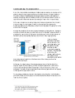
Page 22: ...ates that the processor has missed the first peak above the threshold as it is very fast and short but has caught up shortly afterwards keeping all other peaks under control As it is unable to predict what is coming this will always be a failing with analogue dynamics processing The G2 s ability to predelay the sidechain allows it to predict what will be appearing in the main signal path and react...

Page 23: ... main signal Inserting a delay into the main signal path of an analogue dynamics processor will achieve similar results but with the penalty of delaying the main signal by the amount of look ahead delay introduced Note that the G2 does not have to use this look ahead delay in many cases it is preferable to allow a slower attack For example gating a human voice it is often preferable to have an att...

Page 24: ...m of 25mS to prevent excessive distortion on low frequency signals even with fast attack times and high range settings None the less it is still possible to introduce some distortion if care is not taken with the settings The best way to ensure that the signal is not being excessively distorted is to make good use of the ACTIVE button constantly comparing the original signal with the compressed ve...

Page 25: ... control For example if the ratio is set to 4 1 for every dB the signal drops below the threshold it will be attenuated to a of its normal value How fast this attenuation is applied is controlled by the release control How fast the signal reaches zero attenuation again when it goes over the threshold is determined by the attack control The hold control has no affect in expander mode STEREO Linking...

Page 26: ...r the following equipment in the signal chain and allow extra margin if equalisation sections are boosted Grounding The Screen shield pins on all audio connectors are normally connected directly to the ground pin of the IEC mains inlet The chassis is also directly connected to this pin Never operate this unit without the mains safety ground connected Signal ground 0V is in turn connected to the ch...

Page 27: ...ype 12dB Oct Butterworth Corner Freq 250Hz to 22kHz Parametric Section Type Selectable narrow 0 8 Oct wide 1 43 Oct band pass Centre Freq 20Hz to 20k Gain 8 12 or 20dB and Off Sidechain monitor available Input meter 7 point 18dBu to 18dBu Threshold meter 5 point 16 8 0 8 16dBr to threshold setting Gain Reduction meter 7 point 6dB 6 12 18 24 30 40dB Connectors Inputs 3 pin female XLR Outputs 3 pin ...

Page 28: ... service facility Defects caused by unauthorised modifications misuse negligence act of God or accident or any use of this product that is not in accordance with the instructions provided by XTA are not covered by this warranty This warranty is exclusive and no other warranty is expressed or implied XTA is not liable for consequential damages Options and Accessories Part Number Part Description IT...

Reviews: