background image

Warranty Guide

18

17

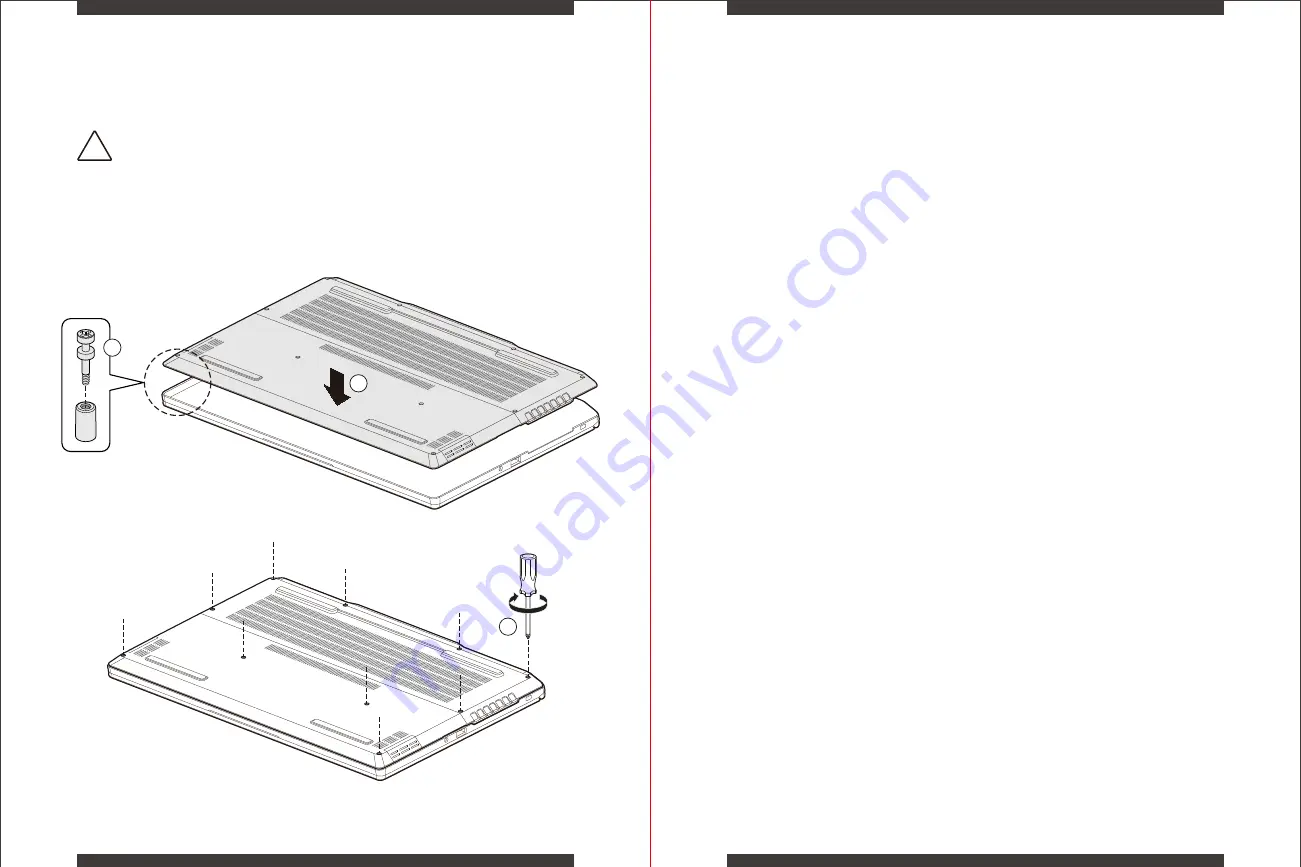
Install Back Cover

In the aim to provide the best Policy for our Customers, XPG grants 1 year Warranty for Your 

Xenia 15 Laptop. 

If the product fails during normal and proper use within the warranty period, XPG will, at its own 

discretion, repair or replace the defective parts within the product, or the product itself, with 

functionally equivalent components as originally supplied.

To start the warranty period validity, users must register their product online at our website 

xpg.com/us/member/login. When a repair request is made after the product has been registered, 

users will have to provide a proof of purchase in the form of an invoice, stamped warranty card or 

delivery receipt to show the purchase date, which will be the start date of the warranty. If there is 

no proof of purchase provided or the product has not been registered, then the product’s date of 

manufacturing will become the effective start date for the warranty period. This date is calculated 

based on the XPG Serial Number printed on the back cover of the product.

Note: Warranty periods and warranty terms may vary depending on different distributing territories. 
Please confirm with the location where the original order was placed to verify.

Warranty Period

Definition of bright dot/black dot:

Bright dot appears as a pixel that is always lit or “ON”. 

If there are any bright dots found within the first 30 days after purchase, the LCD panel 

can be replaced once. 

Black dot appears as a pixel that is always dark or “OFF”, or in an abnormal color.

XPG does not offer at this moment in time a ZERO BLACK DOT FREE service.

LCD Panel

Due to their consumable nature based on use, Battery and the AC Adapter are covered by a 

one-year warranty from the date of purchase, unless specified differently by local regulations. 

Battery and AC Adapter

Software and other accessories that may be bundled with the product are not covered by 

this warranty. A copy of the original pre-installed image as the system was manufactured 

is available as a separate partition on your SSD Drive, should you require to reinstall the 

software from scratch. System recovery can be activated by pressing F8 while powering 

on the system or from an OFF state or can be enabled within the Windows Recovery 

option in Control Panels. 

Our Service Center can provide you with a recovery service and revert your device back to 

its original pre-installed status.

Pre-Installed Software

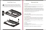
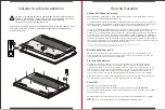
To install the bottom cover of the laptop, lower the cover onto the chassis and align
the 10 captive Phillips screws with the corresponding standoffs. Secure the screws.

Do not remove or replace the back cover with the power on. Always turn 

off the power and unplug the power cord from the system before removing 

or replacing the back cover. Otherwise, the system could be damaged.

!

2

3

1

Summary of Contents for XENIA 15

Page 1: ...MODEL NO XENIA 15 REGULATORY MODEL KC57 XPG XENIA 15 GAMING NOTEBOOK QUICK START GUIDE...

Page 2: ...Quick Start Guide Gu a de Inicio R pido EN ES TC SC 01 2 1 41 61...

Page 3: ...Power On White Power Off Off Suspend Blinking White Touchpad Clickpad Touch sensitive pointing device which functions like a mouse Touchpad Enable Disable Switch with Indicator Double tap to enable or...

Page 4: ...such as a USB flash drive keyboard or mouse 2 in 1 Card Reader Support for SD SDHC SDXC memory cards USB 3 2 Gen2 Port Connect any USB device into this port such as a USB flash drive keyboard or mouse...

Page 5: ...t the AC adapter into this connector Vents The thermal vents are designed to cool the internal components and avoid overheating Thunderbolt 4 Port Connect any USB Type C or Thunderbolt device into thi...

Page 6: ...aution Risk of shock or fire Do not use power cord if damaged Please reach out to place of purchase for replacement 20V AC ADAPTER Power Cord DC Output Plug The display panel can be opened to a wide r...

Page 7: ...Down Press this key combination FN F3 to turn the audio volume down Volume Up Press this key combination FN F4 to turn the audio volume up Press this key combination FN F5 to toggle enable disable fo...

Page 8: ...5mm corner in the top left will enable or disable lighted indicator touchpad functionality You can slide your finger on the static sensitive panel of the touchpad clickpad to move the cursor Press the...

Page 9: ...e sliders There are 2 pre setting can be selected Rainbow Mode Breathing Mode Light Bar System Monitor displays the real time indication of the hardware s system settings The System Monitor s data inc...

Page 10: ...screws securing the cover to the chassis Do not remove or replace the back cover with the power on Always power off and unplug the power cord from the system before removing or replacing the back cove...

Page 11: ...s a pixel that is always lit or ON If there are any bright dots found within the first 30 days after purchase the LCD panel can be replaced once Black dot appears as a pixel that is always dark or OFF...

Page 12: ...rement of substitute goods or services loss of use data or profits business interruption caused by a product that has been physically damaged abused or damaged due to environ mental factors unauthoriz...

Page 13: ...r apagado Suspender blanco intermitente Panel t ctil Dispositivo de se alizaci n sensible al tacto que funciona como un mouse Interruptor de Activaci n Desactivaci n del panel t ctil con indicador Toq...

Page 14: ...unidad flash USB un Lector de tarjetas 2 en 1 Para tarjetas de memoria SD SDHC SDXC Puerto USB 3 2 Gen2 Conecte cualquier dispositivo USB a este puerto como una unidad flash USB un teclado o un mouse...

Page 15: ...necte el adaptador de CA en este conector Rejilla de ventilaci n La ventilaci n t rmica se dise para enfriar los componentes internos y evitar el sobrecalentamiento Puerto Thunderbolt 4 Conecte cualqu...

Page 16: ...del sistema Precauci n Riesgo de descarga o incendio No utilice el cable de alimentaci n si est da ado P ngase en contacto con el lugar de compra para cambiarlo 20V ADAPTADOR DE CA Power Cord DC Outp...

Page 17: ...teclas FN F3 para bajar el volumen del audio Subir volumen Presione esta combinaci n de teclas FN F4 para subir el volumen del audio Presione esta combinaci n de teclas FN F5 para activar des activar...

Page 18: ...superior izquierda se habilitar o deshabilitar la funcionalidad del panel t ctil indicador iluminado Puede usar el panel sensible a la electricidad est tica del panel t ctil y deslizarlo para mover e...

Page 19: ...s Se pueden seleccionar 2 preajustes Modo de arco ris y modo de respiraci n Barra de luces El monitor del sistema muestra la indicaci n en tiempo real de la configuraci n del sistema del hardware Los...

Page 20: ...muestran para desenganchar la cubierta posterior del chasis No retire ni reemplace la cubierta posterior con la alimentaci n encendida Apague la alimentaci n y desenchufe el cable de alimentaci n del...

Page 21: ...l per odo de garant a Esta fecha se calcula en funci n del n mero de serie XPG impreso en la cubierta posterior del producto Nota Los per odos de garant a y los t rminos de garant a pueden variar seg...

Page 22: ...de la naturaleza Esto incluye pero no se limita a adquisici n de bienes o servicios sustituibles p rdida de uso datos o ganancias interrupci n del negocio causada por un producto que ha sido da ado f...

Page 23: ...42 41 A B E F G H I J K L C D B C G H I K J L E A F D LED Windows Hello LED Caps Lock Caps Lock Caps Lock LED Windows LED LED 6 RGB XPG PRIME Lite...

Page 24: ...44 43 A B D C A B C A B C D A B C 2 in 1 SD SDHC SDXC USB 3 2 Gen2 USB USB Kensington USB 3 2 Gen2 USB USB...

Page 25: ...46 45 A C B A A B C A RGB May be controlled through NUC Software Studio D B E C A F A B E F Thunderbolt 4 USB Type C Thunderbolt USB Type C DisplayPort C D HDMI RJ 45 LAN...

Page 26: ...48 47 100 240VAC AC DC DC IN 20V AC ADAPTER DC 180...

Page 27: ...50 49 FN FN esc Fn FN F1 FN F2 FN F3 FN F4 FN F5 FN F7 FN F8 50 FN F9 FN F10 FN F11 FN F12 Bluetooth...

Page 28: ...52 51 FN prt sc FN num lk number lock LED NUM LK 15mm x 15mm x2 LEFT RIGHT...

Page 29: ...54 53 Intel NUC Software Studio Intel NUC Software Studio Windows windows 50 100 60 CPU dGPU 5 LED 0 100 LED CPU iGPU dGPU 12 Aurora RGB Project Aurora https www project aurora com...

Page 30: ...56 55 10 2 2 1 M 2 A NVMe M 2 B SATA NVMe SODIMM A SODIMM B...

Page 31: ...58 57 XPG Xenia 15 XPG xpg com tw member login XPG ON 30 LCD OFF XPG ZERO BLACK DOT FREE LCD AC AC 2 3 1 10...

Page 32: ...60 59 xpg com tw support www xpg com XPG XPG XPG XPG 1 2 3...

Page 33: ...62 61 A B E F G H I J K L C D B C G H I K J L E A F D LED Windows Hello LED LED Windows LED LED 6 RGB...

Page 34: ...64 63 A B D C A B C A B C D A B C SD SDHC SDXC USB 3 2 Gen2 USB U USB 3 2 Gen2 USB U...

Page 35: ...66 65 A C B A A B C D B E C A F A B E F Thunderbolt 4 USB Type C Thunderbolt USB Type C DisplayPort C D HDMI RJ 45 LAN A RGB NUC Software Studio...

Page 36: ...68 67 100 240V 20V AC ADAPTER 180...

Page 37: ...70 69 FN FN ESC FN FN F1 FN F2 FN F3 FN F4 FN F5 FN F7 FN F8 50 FN F9 FN F10 FN F11 FN F12...

Page 38: ...72 71 FN PRT SC FN NUM LK NUM LK 15mm x 15mm x2 LEFT RIGHT...

Page 39: ...Software Studio Intel NUC Software Studio Windows windows 50 100 60 Performance Balanced Battery Saver Balanced CPU dGPU 5 LED 0 100 PWM CPU iGPU dGPU 12 Aurora RGB RGB RGB Project Aurora https www pr...

Page 40: ...76 75 10 1 2 2 1 M 2 A NVMe M 2 B SATA NVMe SODIMM A SODIMM B...

Page 41: ...78 77 XPG Xenia 15 XPG xpg com cn member login XPG ON 30 LCD OFF XPG ZERO BLACK DOT FREE LCD AC AC 10 2 3 1...

Page 42: ...80 79 xpg com cn support www xpg com XPG XPG XPG XPG 1 2 3...

Page 43: ...Regulatory Information 82 81...

Page 44: ...84 83...

Page 45: ...86 85...

Page 46: ...INTEL ASSUMES NO LIABILITY WHATSOEVER AND INTEL DISCLAIMS ANY EXPRESS OR IMPLIED WARRANTY RELATING TO SALE AND OR USE OF INTEL PRODUCTS INCLUDING LIABILITY OR WARRANTIES RELATING TO FITNESS FOR A PAR...

Reviews: