Xpelair VX100 Installation And Maintenance Instructions Manual Download Page 5

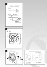
2. CFWG100 - Soffit board termination grille

(white or brown).

3. FD100 / 3 and FD100 / 6 - Flexible ducting.

Where to locate the fan

t

Locate it as high as possible.

t

At least 110mm from the edges of the

mounting surface to the centre of the hole.

t

As far away as possible from and opposite to

the main source of air replacement to ensure

airflow across the room (e.g. opposite the

internal doorway).

t

Near the source of steam or odours.

t

Not where ambient temperatures are likely

to exceed 50˚C.

t

If installed in a kitchen fans must not be

mounted immediately above a cooker hob,

or eye level grill.

t

If installing in a room containing a fuel

burning device which has a non-balanced

flue, it is the installer's responsibility to

ensure that there is enough replacement

air to prevent fumes being drawn down the

flue when the fan is operating up to

maximum extract.

Refer to Building Regulations for specific

requirements.

t

Exhaust air must not be discharged into a

flue used for exhausting of fumes from

appliances supplied with energy other than

electric. Requirements of all authorities

concerned must be observed for exhaust

air discharge and intake flow rates.

t

When intended for use in possible

chemical corrosive atmospheres, consult

out Technical Service Department. (For

overseas markets contact your local

Xpelair distributor).

Installing the isolating switch and cables

1. Check that the electrical rating shown inside

the back plate matches your mains supply.

2. Check there are no buried pipes or cables

e.g. electricity, gas, water behind the switch

location (in the wall or above the ceiling).

If in doubt, seek professional advise.

3. Isolate the mains supply.

4. Lay in the cable from the isolating switch to

the fan location via the on/off switch 

(if required).

5. Lay in the cable from the isolating switch to

the point of connection to the mains supply.

6. Install the isolating switch and on/off switch 

(if required).

7. Make all connections within the isolating

switch and the on/off switch (if required).

5

Note: on/off switch must be situated so that it

cannot be touched by persons making use of

the bath or shower.
WARNING : DO NOT MAKE ANY

CONNECTIONS TO THE ELECTRICAL SUPPLY

AT THIS STAGE.

For Australia only (VX100 & VX100P)

Connection to the supply can be made by a

flexible 2-core cable complete with 3 pin plug for

insertion into an approved 10 amp GPO or

directly wired through an approved 10A wall-

mounted surface switch with at least 3mm

clearance between contacts.

For Australia only (VX100T)

These models are permanently connected to the

supply and operation is controlled by a remote

switch. They should be directly wired to the

supply through an approved 10amp wall mounted

surface switch with at least 3mm clearance

between contacts.

Preparing the hole

If working above ground floor level,

appropriate safety precautions must be

observed.

WARNING: EYE PROTECTION MUST BE

WORN DURING ALL DRILLING AND

CHISELLING OPERATIONS.

If installing in a wall

1. Check there are no buried pipes or cables

in the wall or obstructions on the outside

e.g. electricity, gas, water.

If in doubt, seek professional advise.

2. Mark on the wall the centre of the duct hole.
3. Use this centre to mark a circle to suit the

wall duct (115mm diameter).

If core drill equipment is available:

4a.Use as directed by core drill manufacturer.

If core drill equipment is not available:

4b. Drill a centre hole right through the wall.
5. Cut the hole. Do not cut right through the 

wall. (The recommended method is to drill a 

series of holes, close together, around the 

edge of the cutting line and remove the brick 

between the holes with a chisel).

6. Go outside and cut a hole in the outer wall,

repeating the process described above.

7. Cut ducting to the correct length if required.

The wall tube supplied is telescopic and can

extend to 300mm maximum.

8. Fit the ducting. Ensure that the duct slopes

down away from the fan to allow drainage of

any incoming rain water to the outside.

9. Make good the hole. Allow the mortar to set

before continuing the fan installation.

If installing in a window or panel

1. Cut a hole, 125mm in diameter or if installing

in a window, obtain a ready cut pane.

2. The centre of the hole should be at least

110mm away from the edge of the panel or

pane of glass.

Summary of Contents for VX100

Page 1: ...Installation and maintenance instructions VX100 Standard VX100P Pull Cord VX100T Timer Toilet Bathroom 100mm 4 Fan Range Retain for future reference GB F D ...

Page 2: ...2 B D E F G C 1 2 5 m m 1 1 5 m m ...

Page 3: ...E R TIG HTE NING THE DUC TI NG C AN DISTO R T THE FA N S PIGO T AND CAUSE THE IMPE LLE R TO FO UL ALWAYS CH E CK FAN BLADES RU N SMOOT HLY PR IOR TO OPE R ATIO N DO NOT OVE R TIG HTE N DUC TING ONTO THE SPIGOT THIS CAN R EST R ICT THE MOVE ME NT OF THE FAN BLADES VX100 VX100P VX100T ...

Page 4: ... 44 0 344 879 3588 ...

Page 5: ...h must be situated so that it cannot be touched by persons making use of the bath or shower WARNING DO NOT MAKE ANY CONNECTIONSTOTHE ELECTRICAL SUPPLY ATTHIS STAGE For Australia only VX100 VX100P Connection to the supply can be made by a flexible 2 core cable complete with 3 pin plug for insertion into an approved 10 amp GPO or directly wired through an approved 10A wall mounted surface switch wit...

Page 6: ...ece of the telescopic wall tube onto the ribbed gasket Cut the tube to the required length if necessary 3 If wiring the fan from behind remove knockout Feed the mains cable through the cable entry hole in the back plate to the terminals D 4 If wiring from above leave the cable free to be into labyrinth 5 Insert the lip of the back plate into the wall duct ceiling or vent shaft as before 6 Fasten t...

Page 7: ...it the front cover by aligning it square to the duct and pushing it onto the duct until the release catches snap into the slots on the front cover Using the fan VX100 only t Operate the fan using the switch Repeat to switch o VX100P only t Operate the fan by pulling and releasing the cord Repeat to switch o VX100T only t Operate the fan using the switch When the switch is turned o the fan continue...

Page 8: ... 44 0 344 879 3588 ...

Page 9: ...éférer aux règlements sur la construction t Il ne faut pas décharger l air de refoulement dans un conduit d évacuation prévu pour expulser les fumées provenant d appareils qui ne sont pas alimentés à l électricité Il est impératif de respecter les conditions concernant les débits de d admission et de décharge requises par 9 tous les organismes compétents de réglementation t Si le ventilateur doit ...

Page 10: ... de condensation le cas échéant en le plaÁant aussi près que possible du ventilateur Pour le montage dans le plafond 1 qu il n y a pas de tuyaux ou de câbles dissimulés dans le plafond les solives etc En cas de doute consulter un professionnel qui vous conseillera 2 Découper un trou de 115 mm de diamètre Préparation du ventilateur pour le montage Retirer le couvercle avant Pour cela utiliser un to...

Page 11: ...ement électrique se fait du dessus ne pas xer le câble de pouvoir le monter dans le labyrinthe 5 Introduire la lèvre de la plaque de support dans la gaine du mur plafond ou dans le puits de ventilation comme indiqué précédemment 6 Utiliser les appropriées pour xer la plaque de support sur le mur plafond ou le puits de ventilation Si on utilise des vis ne pas trop les serrer Montage du volet anti r...

Page 12: ...eulement t Pour mettre le ventilateur en marche ou à l arrêt utiliser l interrupteur Marche Arrêt Lorsque l interrupteur est mis sur arrêt le ventilateur continue de fonctionner pendant le délai prédéterminé réglable Nettoyage recommandé une fois par mois UN ELECTRICIEN QUALIFIE DOIT EFFECTUERTOUTES LES OPERATIONS DE NETTOYAGE 1 Avant de nettoyer le ventilateur il faut complètement l isoler de l a...

Page 13: ...13 ...

Page 14: ... 44 0 344 879 3588 ...

Page 15: ...at der Installateur zu gewährleisten dass ausreichend Austauschluft vorhanden ist um zu verhindern dass während des maximalen Absaugbetriebs des Lüfters Dämpfe in das Flammrohr gesogen werden Siehe entsprechende Bauvorschriften 15 t Abluft darf nicht in ein Flammrohr austreten das zum Absaugen von Abgasen anderer Geräte dient die mit anderen Energiearten als Elektrizität betrieben werden Hinsichtl...

Page 16: ...dernis entgraten 4 Das Lüfterrad wieder anbringen Dazu das Lüfterrad auf die Welle setzen und vollständig in Position drücken oder das Netzkabel wird über einen zugelassenen und mit 10 A abgesicherten Wandschalter mit mindestens 3 mm Abstand zwischen den Kontakten direkt verkabelt Gilt nur für Australien VX100T Diese Modelle sind zum permanenten Anschluss an der Spannungsversorgung ausgelegt und i...

Page 17: ...n rechts und unten links anzeichnen 4 Die R ckstauklappe aus der Mauerdurchführung entfernen 5 An den markierten Stellen Schraubenlöcher bohren und die restlichen Wanddübel einsetzen 6 Die oberen und unteren Lüfterblätter aufhalten die Rückstauklappe wieder einsetzen und mit den Schneidschrauben an der Wand sichern Schrauben nicht überdrehen 7 Davon überzeugen dass die Lüfterblätter ungehindert öf...

Page 18: ...sungsmittel benutzen 6 Außer der Reinigung des Lüfters sind keine weiteren Wartungsarbeiten erforderlich 2 Spannungsversorgung abschalten und Sicherungen herausnehmen 3 Das vom Trennschalter kommende Kabel an der Spannungsversorgung anschließen t Bei Stromkreisen mit fest verlegten Kabeln darf die Nennstromstärke der Gerätesicherung 5 A nicht überschreiten Nur VX100T I t Zum Einstellen des Overrun...

Page 19: ...19 ...

Page 20: ...pe Limited Millbrook House Grange Drive Hedge End Southampton SO30 2DF Airport Road Cloghran Co Dublin K67 VE08 Telephone 44 0 344 879 3588 Telephone 353 0 1 8523400 Email customer services glendimplex com Email serviceireland glendimplex com Web www xpelair co uk ...

Reviews: