3
6
CAUTION:all the parts in the schematic diagram marked with shodows and the signs of
are extremely
important for safety. In case of replacement of any part of components. Be sure to consult the service manual
carefully.
1. the schematic diagram is characteristic. The various valus in the electric circuits are basic data, which are
changeable according to the various basic circuits.
2. testing waves are abtained by inputing the standard color bar of the signed.
3. resistance unit is in Ohm, namely: K=1000; M=1000K; Capacitance unit is in µF; P=µµF(µ=10
6
)
4. Unless othervise noted inside, all resistors are 1/6W, the withstand voltage of all capacitor are 50V.
5. Inductance unit is in µH.
6. The
mark
in the diagram means Ferrite ring
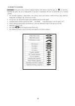
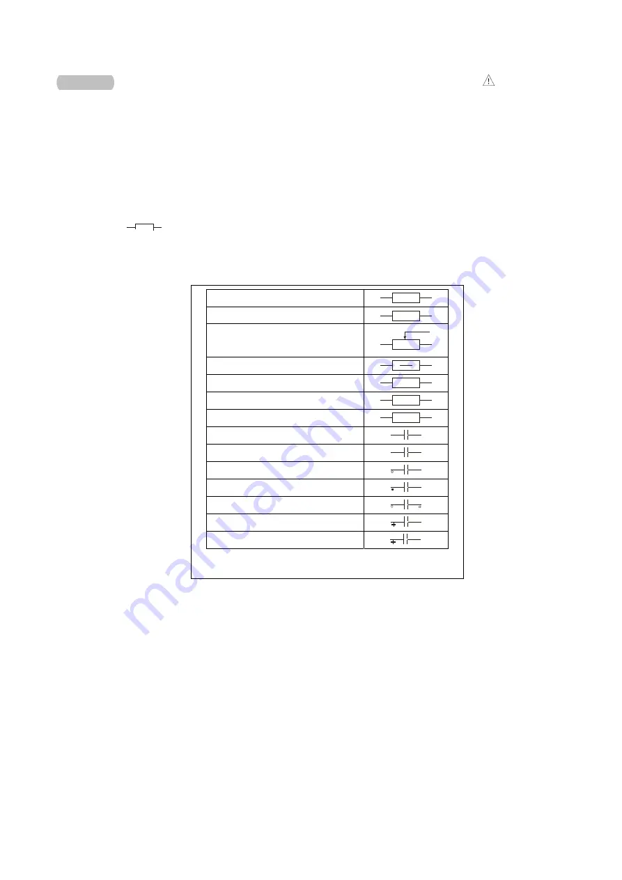
7. The symbols of various types of resistors and capacitors are listed as follows:
Carbon film resistor
Metal film resistor
M
Potentiometer resistor
1/2w resistor
1w resistor
1
2w resistor
2
3w resistor
3
Ceramic capacitor
AC Ceramic capacitor
AC
Terylene capacitor
Polypropylene capacitor
Metal Terylene capacitor
Aluminium electrolyse capacitor
Tantalum electrolyse capacitor
T
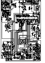
SCHEMATIC DIAGRAM
Summary of Contents for TS2050J
Page 1: ...COLOR TELEVISION TK2050 TS2050J...
Page 17: ...15 Wiring diagram...
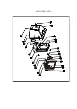
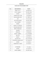
Page 35: ...EXPLODED VIEW...
Page 38: ......

