8
Working principle:
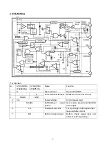
The unit adopts the super single IC R2J10165(N102) with I2C bus controlled processor produced by
RENE
s
AS, which includes IF, color decoder, 8-bits MCU, pre-video amplify, H/V deflection, AV switch,
audio processing, ect.. The main interfaces are: one AV IN, one S-VIDEO IN, YCbCr, one AV OUTPUT.
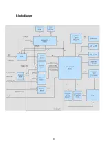
The signal flow is below:
The antenna reception signal RF will be sent to the integrative tuner (contains HF and IF amplifier
circuits), which is controlled by SDA and SCL, selects appropriate channel and sends the selected IF
signal to the next level for processing.
If receive the analog RF signal, RF will be sent to tuner, via HF and mixing, output IF, via V111 after, it
sent to SAW Z101 filtering and gain better IF. Then it feed to main IC N102 (R2J10165) from 38#, 39# IF
amplify, phase-lock loop VCO and synchronous detection, output from 34# as composite video signal
VIF-VIDEO. After filtering, VIF-VIDEO changes to VIDEO-TV.
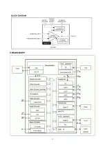
If receive the digital RF signal, the signal via HF and IF amplifying, output differential digital IF signal
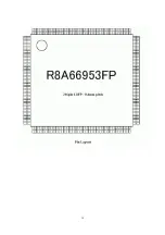
form 10#, 11#, then feed to NH07(R8A66953) demodulate and MPEG decoder, output YCbCr of
DTV( DTV-Y and DTV-CbCr) and audio DTV-L/R.
VIDEO-TV, DTV-Y, Y component from YCbCr and V/Y signal of AV1/S, AV2 selected by switch NB04
(TC4053), they are all sent to NB01(TC4052)9#,10# select, output VIDEO, it will be sent to N102 form
32#. C of S terminal is sent to N102 30#. Components Cb, Cr and DTV-CbCr demodulated and MPEG
decoded by R8A66953 are sent to N102 19#,20#, then switch selection, video decoding and processing,
it sent to the internal RGB interface matrix, pre-video amplify, contrast, bright and blacking, output RGB
form 51#,52#,53#. After N102 internal video switch selecting, the video is sent to decoding and
processing, it also output from 24# as AV OUT.
The main IC N102 has the H/V deflection internal. VDRV output from 11#, via N301(TDA8172)
amplifying to push the vertical deflection coil. HDRV output from 15#, via V301(ST1803DF) driving to
push the horizontal deflection coil. EW-OUT output form 25# via V303(2SC3852) driving then sent to the
horizontal deflection.
The IF signal is sent to N102 from 38# 39# demodulating TV audio L/R. L/R of AV1/S, AV2 via audio
switch NB04(TC4053) selecting, L/R of YCbCr and DTV-L/R demodulated and MPEG decoded by
R8A66953, it sent to N102 29#,43# switch selection and audio process together with TV audio signal,
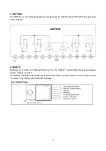
then output L/R from 46# 48#, it sent to sound amplifier NV01(AN7522) amplifying to push the speaker;
at the same time, the L/R from 46# 48# is also audio of AV OUT.
The unit is control by the MCU built in N102, it connects tuner and E2PROM through IIC bus line and
controls the whole unit working.
Summary of Contents for TQ2426
Page 1: ...COLOR TELEVISION TQ2426 ...
Page 11: ...Block diagram 9 ...
Page 12: ...10 IC Block diagram 1 R2J1016XFP ...
Page 15: ...13 5 R8A6695SFP ...
Page 16: ...14 ...
Page 17: ...15 ...
Page 20: ......
Page 21: ......
Page 22: ......
Page 24: ...603 TQ24260 10 Ver 1 0 ...

