background image

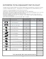
DUCT PIECE          DESCRIPTION                           MULTIPLIER        QTY USED          

1’ of 8” Round Duct

1’ of 4“ x 14” Rect. Duct 

8” 90 Degree Elbow

8” 45 Degree Elbow

4” x 14” 90 Degree 

4” x 14” 45 Degree 

4” x 14” x 8” Round 

4” x 14” x 8” Round 90 Degree 

8” Round Wall Cap w Damper

4” x 14” 90 Wall cap w Damper

8” Round Roof Cap  


1

1

12

7

14

8

2

4

24

24

33


TOTAL EQUIVALENT FEET SHOULD BE LESS THAN 100

CAUSING AIR TO CHANGE DIRECTION CAUSES TURBULENCE AND RESTRICTS FLOW IN A SYSTEM. 

IF USING FLEXIBLE METAL DUCT - INCREASE ALL MULTIPLIERS BY 50% (12 BECOMES 18 - ETC.)


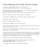
THIS EASY TO USE WORKSHEET IS FOR 1000 CFM OR LESS.

UNDER “QTY USED” ENTER HOW OF EACH SECTION YOU WILL BE USING.

IN THE FIRST TWO ROWS - ENTER HOW MANY FEET OF EACH TYPE OF STRAIGHT DUCT YOU WILL 

BE USING (I.E. FOR 20 FT ENTER 20, FOR 30’ ENTER 30).

ENTER THE NUMBER OF EACH TYPE OF TURN YOU ARE USING AND THE TYPE OF END CAP.

MULTIPLY ACROSS EACH ROW THE “MULTIPLIER” x “QTY USED” TO GET THE EQUIVALENT FEET 

FOR THOSE COMPONENTS.

ADD UP ALL THE VALUES IN THE “EQUIVALENT FEET” COLUMN.


estimating total equivalent feet in a duct

EQUIVALENT

FEET

9

Summary of Contents for XOIL4819KS

Page 1: ...I worked really hard on this manual so please read it XOIL INSERT LINER MODELS XOIL4819KS ...

Page 2: ... Before you proceed take just a moment to register your XO at Ensuring warranty coverage should you need service Providing ownership verification for insurance purposes Let s XO notify you in the event of product changes or recalls www xoappliance com register your product REGISTRATION HELPS YOU BY there are 2 ways to contact our ventilation experts Online https xoappliance com priority service fo...

Page 3: ... Safety and Precautions Planning Ductwork Install Examples Dimensions THE INSTALL 12 17 Mounting Height Top or Rear Exhaust Cut Out Dimensions Installing Electrical Connections MAINTENANCE 18 19 Filters Cleaning Light Replacement OPERATING 20 The Push Button Controls Synchronizing the Remote PARTS WARRANTY 21 23 ...

Page 4: ...ordance with all applicable codes and standards including fire rated construction chimney of the fuel burning equipment to prevent backdrafting Follow the cooking equipment manufacturer s guidelines and safety standards such as those published by the National Fire Protection Association NFPA and the American Society of Heating Refrigeration and Air Conditioning Engineers ASHRAE as well as all loca...

Page 5: ...safety first continued 5 ...

Page 6: ...safety first continued 6 ...

Page 7: ...safety first continued 7 ...

Page 8: ... chart WHEN YOU MUST USE FITTINGS TRY TO SEPARATE THEM WITH SECTIONS OF 4 OR MORE OF STRAIGHT DUCT ALWAYS FOLLOW THE MANUFACTURER S GUIDELINES FOR THE COOKING EQUIPMENT YOU ARE VENTING IF MAKE UP AIR CONTROL DAMPERS ARE REQUIRED POSITION THE SENSOR IN A STRAIGHT RUN OF DUCT IDEALLY WITH 4 OF STRAIGHT DUCT BETWEEN EACH SIDE OF THE SENSOR AND A DUCT FITTING REMEMBER TO INCLUDE POWER AND CONTROL WIRI...

Page 9: ... A SYSTEM IF USING FLEXIBLE METAL DUCT INCREASE ALL MULTIPLIERS BY 50 12 BECOMES 18 ETC THIS EASY TO USE WORKSHEET IS FOR 1000 CFM OR LESS UNDER QTY USED ENTER HOW OF EACH SECTION YOU WILL BE USING IN THE FIRST TWO ROWS ENTER HOW MANY FEET OF EACH TYPE OF STRAIGHT DUCT YOU WILL BE USING I E FOR 20 FT ENTER 20 FOR 30 ENTER 30 ENTER THE NUMBER OF EACH TYPE OF TURN YOU ARE USING AND THE TYPE OF END C...

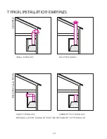
Page 10: ...typical installation examples 10 WALL EXHAUST ROOF EXHAUST SOFFIT EXHAUST CABINET TOP EXHAUST RECIRCULATION EXHAUST MUST BE RETURNED TO THE SPACE RECIRCULATION VENTED ...

Page 11: ...dimensions 11 40 3 8 12 3 5 31 32 46 3 8 12 19 1 4 Ø7 27 32 Front of hood Side of hood Top of hood A B MODEL DIM A DIM B XOIL48KS ...

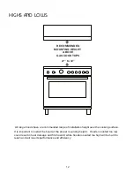
Page 12: ...king surface RECOMMENDED MOUNTING HEIGHT ABOVE GAS COOKTOPS 27 to 32 It is important to install the hood at the proper mounting height Hoods mounted too low could result in heat damage and fire hazard while hoods mounted too high will be hard to reach and will lose its performance and efficiency ...

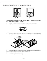
Page 13: ...uick disconnect coupling that supplies power to the motor 2 Remove the eighteen 18 screws that fasten the blower assembly and filler plate to the hood 3 Remove the blower assembly and filler plate invert 180 as shown and fasten in place using the eighteen 18 screws previously removed 4 Reconnect the quick disconnect plug 180 o ...

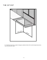
Page 14: ...the cut out 14 To install the hood into a custom canopy or cabinet refer to the cutout dimensions above for your particular model 46 1 2 19 7 16 ...

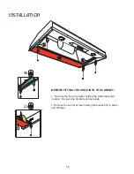
Page 15: ... B B H H 2x BEFORE FITTING THE HOOD INTO THE CABINET 1 Remove the four 4 screws holding the side bracket B in place Remove the brackets and set aside 2 Remove the two 2 screws holding the bracket H in place and tilt down ...

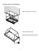
Page 16: ...installation continued 16 1 4 1 1 8 8x INSERT THE HOOD INTO THE CUTOUT FASTEN THE HOOD IN PLACE Using four 4 screws along the inside front edge and four 4 screws in the back corners as shown ...

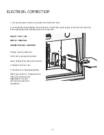
Page 17: ...line to the appropriate wire following this color convention BLACK HOT LEG WHITE NEUTRAL GREEN YELLOW GROUND Polarity must be observed Unit must be properly grounded Use a double throw disconnect switch 3 Replace the box cover 4 Replace the Anti grease Baffles All wiring must be in compliance with nathional electrical code ANSI NFPA 70 1999 and all local codes and regulations ...

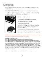
Page 18: ...tical to minimize the risk of fire Baffle filters should be cleaned at least once every 2 months more frequently depending on the type of cooking performed and the build up of grease CLEANING STAINLESS STEEL Do not use corrosive detergents abrasive detergents or oven cleaners Do not use any product containing chlorine bleach or any product containing chloride Do not use steel wool or abrasive scru...

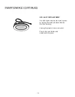
Page 19: ...continued 19 LED LIGHT REPLACEMENT The LED light modules are held in place by spring clips and pull down directly from the housing Unplug the plastic molex connector Plug in the new fixture and snap back into place ...

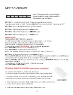
Page 20: ...od is off BUTTON T Activates and Deactivates the TIMER Function Pressing BUTTON T whether the blower is off or running will cause the motor to run at LOW speed for 5 minutes before shutting off the blower and lights automatically While the TIMER is activated you can change speed or engage POWER BOOST the hood will still shut off after 5 minutes To manually turn the the unit off before 5 minutes ha...

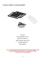
Page 21: ...ies 21 ALL OF THESE PARTS AND MORE ARE AVAILABLE SIMPLY VISIT WWW XOAPPLIANCE COM and click on PARTS STORE OR CALL US AT 973 403 8900 FILTERS REPLACEMENT LIGHTS REMOTE CONTROLS REPLACEMENT SWITCHES BLOWER MOTORS FAN WHEELS ...

Page 22: ...notes 22 ...

Page 23: ...commercial applications are excluded from these warranties WARRANTY IS NOT TRANSFERABLE This warranty is not assignable and applies only in favor of the original purchaser user at the original installation location Any such assignment or transfer shall void the warranties herein made and shall void all warranties express or implied including any warranty or merchantability or fitness for a particu...

Page 24: ...XO APPLIANCE 24 EISENHOWER PARKWAY ROSELAND NJ 07068 www xoappliance com p 973 403 8900 ...

Reviews: