


Wi-Fi Array
Installing the Wi-Fi Array
41
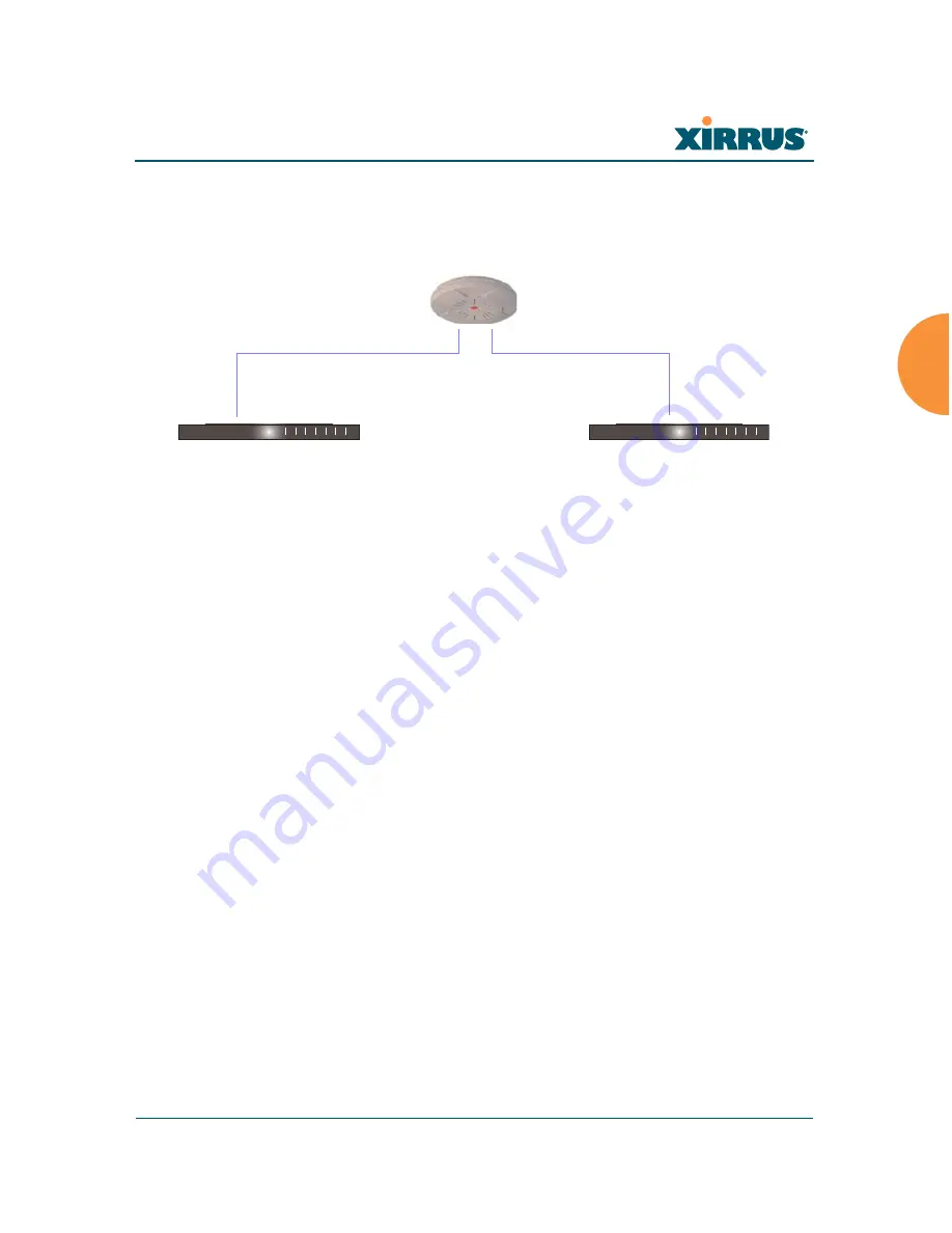
Switch Failover Protection
To ensure that service is continued in the event of a switch failure, you can
connect Arrays to more than one Ethernet switch (not a hub).
Figure 21. Switch Failover Protection
See Also
Coverage and Capacity Planning
Deployment Examples
Installation Prerequisites
Network Management Planning
Planning Your Installation
Power Planning
Security Planning
#
Gigabit Ethernet connections must be on the same subnet.
Ethernet switch
Backup switch
Ethernet connections
Summary of Contents for Wi-Fi Array XN16
Page 1: ...June 10 2008 ...
Page 2: ......
Page 34: ...Wi Fi Array x Table of Contents ...
Page 40: ...Wi Fi Array xvi List of Figures ...
Page 65: ...Wi Fi Array Introduction 25 ...
Page 66: ...Wi Fi Array 26 Introduction ...


