81
First read the U0-60 (0x1041) value
(1)
0
means
running
in
the
positive
direction.
The
current
encoder
value
is
U0-57*1+U0-58*2^16+U0-59*2^32.
(2) 1 means running in the opposite direction. The current encoder value is: (U0-57-65535)*1+
(U0-58-65535)*2^16+ (U0-59-65535)*2^32.
Communication parameter description
RS485 default communication parameters: baud rate 19200 bps; data bit 8; stop bit 1; even parity;
Modbus station number 1.
Note: Refer to Appendix 1 (P7-XX) for communication parameter description.
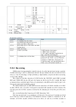
5.12 I/O signal
5.12.1 Servo alarm output
(
/ALM
)
and alarm reset
(
/ALM-RST
)
Servo alarm output /ALM
Parameter Signal
Default
setting
Suitable
mode
Meaning
Modify
effective
P5-47
/ALM
n.0002
All
Output normally open signal
from SO2 terminal
anytime
At once
When the servo driver is powered on, detecting abnormality will output alarm signal.
Alarm reset /ALM-RST
Parameter Signal
Default
setting
Suitable
mode
Meaning
Modify
effective
P5-24
/ALM-
RST
n.0002
All
Input normally open signal
from SI2 terminal
anytime
At once
1. The parameter range is 0000-0014, which is allocated to other input terminals through parameter
P5-24.
2. When an alarm occurs, find out the cause of the alarm and remove it, then clear the alarm by setting
the signal to be effective.
3. /ALM-RST signal can be assigned to other terminals through this parameter, because the alarm signal
is related to the safe operation of the servo, so the /ALM-RST signal can not be set to be always valid
(n.0010).
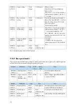
5.12.2 Warn output
(
/WARN
)
Set the alarm output threshold, when the current speed is higher than the warning speed, output /
WARN.
Parameter
Meaning
Default
value
Unit
Range
Modify
Effective
P3-19
Forward warning
speed
Motor
related
rpm
0
~
65535
Servo
OFF
At once
P3-20
Reverse warning
speed
Motor
related
rpm
0
~
65535
Servo
OFF
At once


