Xilinx Virtex-6 FPGA Getting Started Download Page 61

Virtex-6 Getting Started Guide

www.xilinx.com

61

UG533 (v1.4) November 15, 2010

Installing the ISE Software

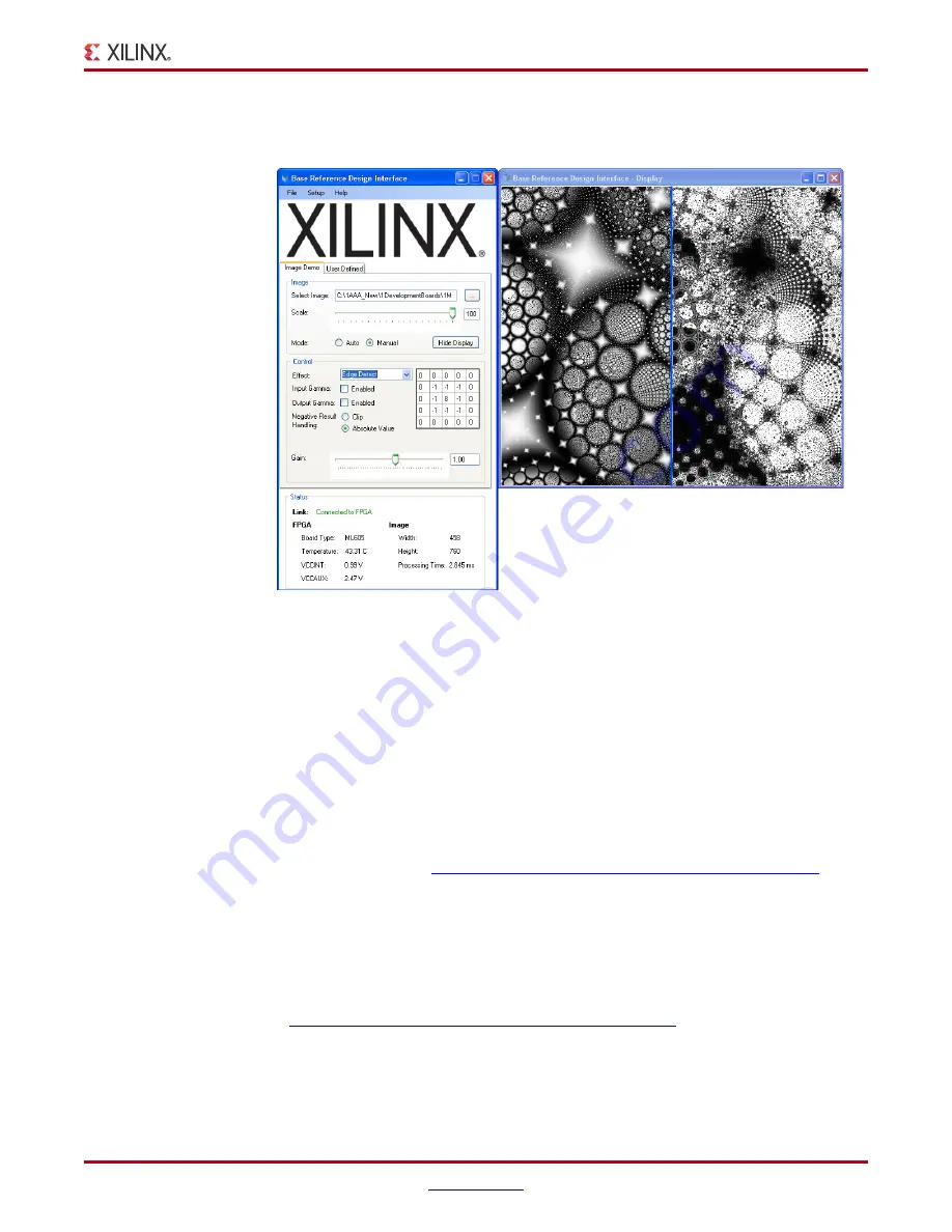
Choose Edge Detect from the effect menu. The filtering transform shown in 

Figure 1-60


will be displayed. 

Different effects can be set automatically by selecting the 

Auto

 mode button.

FPGA temperature, VCCINT, VCCAUX, Image dimensions, and processing time are also 
reported by the Status field. 

You have now completed running the reference design.

Installing the ISE Software

The ML605 evaluation kit includes entitlement to a seat that permits the 
ISE Design Suite: Logic Edition to be used with a Virtex-6 XC6VLX240T-1FFG1156C FPGA. 
This software can be installed from the DVD provided with the kit. The latest version can 
also be downloaded from 

http://www.xilinx.com/support/download/index.htm

.

The ML605 evaluation kit also works with the software listed here:

ISE Design Suite: Embedded Edition

ISE Design Suite: DSP Edition

ISE Design Suite: System Edition

Update the software before working with the evaluation kit. Updates can be downloaded 
from 

http://www.xilinx.com/support/download/index.htm

To install the ISE Design Suite: Logic Edition software from the DVD included with the 
ML605 evaluation kit:

1.

Activate the software license. See 

“Redeeming the Software and IP License.”

X-Ref Target - Figure 1-60

Figure 1-60:

Original and FPGA Filtered Images using Edge Detect Effect

Summary of Contents for Virtex-6 FPGA

Page 1: ...Guide Subtitle optional UG533 v1 4 November 15 2010 optional Getting Started with the Xilinx Virtex 6 FPGA ML605 Evaluation Kit UG533 v1 4 November 15 2010 XPN 0402771 01...

Page 2: ...XPRESS IMPLIED OR STATUTORY REGARDING THE DOCUMENTATION INCLUDING ANY WARRANTIES OF MERCHANTABILITY FITNESS FOR A PARTICULAR PURPOSE OR NONINFRINGEMENT OF THIRD PARTY RIGHTS IN NO EVENT WILL XILINX BE...

Page 3: ...System Properties 12 Configuring the FPGA 15 Running the BIST Application 17 Getting Started with PCI Express PIO Demonstration 28 System Requirements Installation and Setup 29 Running the PCI Expres...

Page 4: ...4 www xilinx com ML605 Evaluation Kit Getting Started Guide UG533 v1 4 November 15 2010...

Page 5: ...ication includes the tables for device package combinations and maximum I Os pin definitions pinout tables pinout diagrams mechanical drawings and thermal specifications Virtex 6 FPGA Configuration Gu...

Page 6: ...SP48E1 slice in Virtex 6 FPGAs and provides configuration examples Virtex 6 FPGA System Monitor User Guide The System Monitor functionality available in all Virtex 6 devices is outlined in this guide...

Page 7: ...nine cards Integrated tools help streamline the creation of elegant solutions to complex design requirements This document provides Introduction to the board s features Instruction for default hardwar...

Page 8: ...AG 16 MB Platform Flash XL 32 MB Parallel BPI Flash System ACE CompactFlash CF controller Communication and Networking 10 100 1000 Tri Speed Ethernet GMII RGMII SGMII MII SFP transceiver connector GTX...

Page 9: ...V 1 2V and 1 0V supplies Getting Started with the Flash Demonstration Before installing the software you can run some of the demonstration designs that are pre installed on the BPI Flash Platform Flas...

Page 10: ...DVI Output User Clock J55 J58 BPI Flash U4 System ACE Address GPIO LEDs UG533_01_01_121709 X Ref Target Figure 1 2 Figure 1 2 Default Jumper and Switches Settings J69 J18 J65 J42 J66 J67 J68 J54 J19 J...

Page 11: ...t the cables and power 1 Connect one USB Type A to mini B 5 pin cables from your PC to J21 on the ML605 board 2 Power on ML605 board for UART Drivers Installation a Install the CP210x VCP Win2K XP 2K3...

Page 12: ...er 15 2010 Getting Started with the Flash Demonstration Setting the System Properties 3 Right click My Computer and select Properties a Select the Hardware tab b Click on Device Manager X Ref Target F...

Page 13: ...533 v1 4 November 15 2010 Getting Started with the Flash Demonstration 4 Expand the Ports Hardware a Right click on USB to UART Bridge and select Properties X Ref Target Figure 1 5 Figure 1 5 Select t...

Page 14: ...the COM Port to an open Com Port setting from COM1 to COM4 6 Start the Tera Terminal Program downloadable from http www ayera com teraterm a Select your USB com port from the Port drop down window b S...

Page 15: ...000 position 4 to position 1 8 Insert the CompactFlash card into the card reader and press SW3 the System ACE Reset pushbutton The CompactFlash card contains a Built In System Test BIST design which i...

Page 16: ...v1 4 November 15 2010 Getting Started with the Flash Demonstration 9 After FPGA configuration a menu of feature tests appears as shown in the Tera Terminal window Figure 1 10 X Ref Target Figure 1 10...

Page 17: ...IST Application Typing any number or character between 1 to D makes the bootloader copy the associated software application to the external DDR3 SODIMM memory and run it 10 Type a 1 to start the UART...

Page 18: ...e UG533 v1 4 November 15 2010 Getting Started with the Flash Demonstration 12 Type a 3 to start the Timer test 13 Type a 4 to start the flash test X Ref Target Figure 1 13 Figure 1 13 3 Timer Test X R...

Page 19: ...Started with the Flash Demonstration 14 Type a 5 to start the IIC EEPROM test 15 Type a 6 to start the Ethernet Loopback Temac test This takes approximately 10 seconds to complete X Ref Target Figure...

Page 20: ...inx com Virtex 6 Getting Started Guide UG533 v1 4 November 15 2010 Getting Started with the Flash Demonstration 16 Type a 7 to start the GPIO Switch test X Ref Target Figure 1 17 Figure 1 17 7 GPIO Sw...

Page 21: ...G533 v1 4 November 15 2010 Getting Started with the Flash Demonstration 17 Type an 8 to start the External Memory Multi Port Memory Controller MPMC test This takes approximately 20 minutes to complete...

Page 22: ...xilinx com Virtex 6 Getting Started Guide UG533 v1 4 November 15 2010 Getting Started with the Flash Demonstration Figure 1 19 shows the MPMC test status X Ref Target Figure 1 19 Figure 1 19 MPMC Test...

Page 23: ...ing Started Guide www xilinx com 23 UG533 v1 4 November 15 2010 Getting Started with the Flash Demonstration 18 Type a 9 to start the System Monitor test X Ref Target Figure 1 20 Figure 1 20 9 System...

Page 24: ...ith the Flash Demonstration 19 Type an A to test the North South East West and Center pushbuttons as shown in Figure 1 21 Figure 1 22 shows the test menu X Ref Target Figure 1 21 Figure 1 21 ML605 Nor...

Page 25: ...irtex 6 Getting Started Guide www xilinx com 25 UG533 v1 4 November 15 2010 Getting Started with the Flash Demonstration 20 Type a B to start the LCD test X Ref Target Figure 1 23 Figure 1 23 LCD Test...

Page 26: ...nx com Virtex 6 Getting Started Guide UG533 v1 4 November 15 2010 Getting Started with the Flash Demonstration 21 Type a C to start the System ACE CF test X Ref Target Figure 1 24 Figure 1 24 System A...

Page 27: ...L605 board using the connector shown in Figure 1 25 The DVI VGA adapter provided in the ML605 Evaluation Kit can be used to connect a VGA monitor 23 Type a D to start the DVI VGA TFT test The test pat...

Page 28: ...m host CPU to access Memory Mapped Input Output MMIO and Configuration Mapped Input Output CMIO locations in the PCI Express fabric Endpoints for PCI Express accept Memory and IO Write transactions an...

Page 29: ...that can be used for checking the presence of PCI devices in PCIbus Software Installation and Setup 1 Download the free PciTree tool Figure 1 28 from http www pcitree de download html 2 Unzip PCItree...

Page 30: ...igure 1 29 S2 is set to 011001 This will configure the FPGA from the Platform Flash XL device using Slave SelectMAP and the onboard external oscillator for CCLK J42 should also have a shunt on pins 5...

Page 31: ...and wait for your ML605 board to power up consequently 10 The x8 PCI Express PIO design is pre loaded on the ML605 board s Platform Flash XL Upon the board s power up and successful configuration of...

Page 32: ...r 15 2010 Getting Started with PCI Express PIO Demonstration Configuration Registers Test 12 Set the number of configuration registers to 64 as shown in Figure 1 31 and click on the refresh dump butto...

Page 33: ...mber 15 2010 Getting Started with PCI Express PIO Demonstration 13 Locate the Xilinx device as shown in figure Figure 1 32 Xilinx PCI vendor ID is 0x10EE Device ID of the x8 Gen1 configuration is 0x60...

Page 34: ...igate to the linked list in the configuration space as shown in Figure 1 33 to locate the PCIe capabilities structure 15 With the Xilinx device selected select register 0x40 Register 0x40 points to th...

Page 35: ...ith PCI Express PIO Demonstration 16 Select register 0x48 as shown in Figure 1 34 Register 0x48 points to the next structure 0x60 is the address of the next structure indicating the data at this offse...

Page 36: ...Getting Started Guide UG533 v1 4 November 15 2010 Getting Started with PCI Express PIO Demonstration 17 Select register 0x60 as shown in Figure 1 35 0x60 is a type 0x10 X Ref Target Figure 1 35 Figure...

Page 37: ...register 0x6C Link Capabilities Register Figure 1 36 Indicates the maximum number of lanes and speed supported The value 0x81 shows this is an x8 Gen1 capable device The Link Status Register 0x70 show...

Page 38: ...Express PIO Demonstration Base Address Register BAR Test 19 Double click on BAR 0 as shown in Figure 1 37 BAR 0 address is machine dependent 20 Click Yes on the dialog box as shown in Figure 1 38 X Re...

Page 39: ...rted Guide www xilinx com 39 UG533 v1 4 November 15 2010 Getting Started with PCI Express PIO Demonstration 21 Select auto read memory as shown in Figure 1 39 X Ref Target Figure 1 39 Figure 1 39 Sele...

Page 40: ...UG533 v1 4 November 15 2010 Getting Started with PCI Express PIO Demonstration 22 Click on the first memory location by holding Shift End keys This will select 1024 bytes as shown in Figure 1 40 X Ref...

Page 41: ...Getting Started with PCI Express PIO Demonstration 23 Write to memory by selecting the count box and Write Memory button as shown in Figure 1 41 24 Verify the result counting up to FF by selecting the...

Page 42: ...10 Getting Started with PCI Express PIO Demonstration 25 Restore the memory by deselecting the count box and clicking the Write Memory button as shown in Figure 1 42 26 Review the result by clicking o...

Page 43: ...ered images in the DDR3 SDRAM These images are sent from a PC via a series of Ethernet packets This memory controller is continuously reading filtering and storing images back into this memory The PC...

Page 44: ...ion address 3 on the CF card 6 Do not change any other factory default settings 7 Power on the ML605 Installing Base Reference Design Application GUI The Base Reference Design includes an application...

Page 45: ...Virtex 6 Getting Started Guide www xilinx com 45 UG533 v1 4 November 15 2010 Getting Started with the Base Reference Design Click Run X Ref Target Figure 1 44 Figure 1 44 Run BRD GUI Installer...

Page 46: ...inx com Virtex 6 Getting Started Guide UG533 v1 4 November 15 2010 Getting Started with the Base Reference Design Click Next to run the BRD Setup Wizard X Ref Target Figure 1 45 Figure 1 45 BRD Interf...

Page 47: ...tex 6 Getting Started Guide www xilinx com 47 UG533 v1 4 November 15 2010 Getting Started with the Base Reference Design Click Next X Ref Target Figure 1 46 Figure 1 46 Install Required WinPcap Compon...

Page 48: ...com Virtex 6 Getting Started Guide UG533 v1 4 November 15 2010 Getting Started with the Base Reference Design Confirm the Installation by clicking Next X Ref Target Figure 1 47 Figure 1 47 Confirm BRD...

Page 49: ...Virtex 6 Getting Started Guide www xilinx com 49 UG533 v1 4 November 15 2010 Getting Started with the Base Reference Design X Ref Target Figure 1 48 Figure 1 48 BRD Installation in Progress...

Page 50: ...50 www xilinx com Virtex 6 Getting Started Guide UG533 v1 4 November 15 2010 Getting Started with the Base Reference Design Click Next X Ref Target Figure 1 49 Figure 1 49 Launch WinPcap Installer...

Page 51: ...Virtex 6 Getting Started Guide www xilinx com 51 UG533 v1 4 November 15 2010 Getting Started with the Base Reference Design Click Next X Ref Target Figure 1 50 Figure 1 50 WinPcap Installation Wizard...

Page 52: ...ting Started Guide UG533 v1 4 November 15 2010 Getting Started with the Base Reference Design Click I Agree if you agree with the WinPCAP license terms and conditions X Ref Target Figure 1 51 Figure 1...

Page 53: ...6 Getting Started Guide www xilinx com 53 UG533 v1 4 November 15 2010 Getting Started with the Base Reference Design Click Finish X Ref Target Figure 1 52 Figure 1 52 WinPcap Installation Wizard Succ...

Page 54: ...54 www xilinx com Virtex 6 Getting Started Guide UG533 v1 4 November 15 2010 Getting Started with the Base Reference Design Click Close X Ref Target Figure 1 53 Figure 1 53 BRD Installation Complete...

Page 55: ...the Ethernet cable connected between the ML605 board and your PC Ethernet port Note Turn off any wireless cards while running this demonstration To start the application GUI please go to your Windows...

Page 56: ...se Reference Design Select the menu item Setup then select the appropriate Wired Network Wait for few seconds and then press SW3 on the ML605 to configure the FPGA using the System ACE CF controller a...

Page 57: ...tarted with the Base Reference Design You can now select an image It is best to select an image smaller than 1024 pixels wide On the USB flash drive there are a number of images to select or you can s...

Page 58: ...GUI use the browse button to navigate to an image After you have selected the image click the Show Display button This will display two side by side images The leftmost image is the unaltered image an...

Page 59: ...eference Design Using the pull down menu select a different effect For example select SobelX The filtering transform will display As you can see in Figure 1 58 the image is updated using the selected...

Page 60: ...tting Started with the Base Reference Design Select Smooth effect and notice how the 2 D FIR filter coefficient matrix values change Figure 1 59 shows how the image display changes as well X Ref Targe...

Page 61: ...used with a Virtex 6 XC6VLX240T 1FFG1156C FPGA This software can be installed from the DVD provided with the kit The latest version can also be downloaded from http www xilinx com support download ind...

Page 62: ...re Redeeming the Software and IP License A software voucher similar to the example shown in Figure 1 61 is included with each ML605 evaluation kit The voucher contains the code that is used to create...

Page 63: ...t to create one Note If you have questions or need help contact Xilinx customer service at http www xilinx com support techsup tappinfo htm 3 After signing in confirm your contact information is corre...

Page 64: ...checked for licensing as shown in Figure 1 64 Note The software descriptions shown in Figure 1 64 are examples and might differ from the descriptions shown on the actual page 5 Click Generate Node Loc...

Page 65: ...license select a host ID The host ID can be a dongle serial number Ethernet MAC address or a disk volume ID 7 When license generation is complete the license will be emailed to you Follow the instruct...

Page 66: ...License Configuration Manager dialog and click Copy License Figure 1 66 9 Navigate to the location where the Xilinx lic file is saved and select it Figure 1 67 X Ref Target Figure 1 65 Figure 1 65 Xi...

Page 67: ...nstrations You now have a complete and updated installation of the Xilinx ISE Device Locked to Virtex 6 LX240T FPGA software and should have been able to open your first project Additional resources a...

Page 68: ...vice Representative Canada USA and South America isscs_cases xilinx com Europe Middle East and Africa eucases xilinx com Asia Pacific including Japan apaccase xilinx com For technical support includin...

Page 69: ...lect or default of Customer For any breach by Xilinx of this limited warranty the exclusive remedy of Customer and the sole liability of Xilinx shall be at the option of Xilinx to replace or repair th...

Page 70: ...70 www xilinx com Virtex 6 Getting Started Guide UG533 v1 4 November 15 2010 Warranty...

Page 71: ...t Specifications 11 UG366 Virtex 6 FPGA GTX Transceivers User Guide 12 UG369 Virtex 6 FPGA DSP48E1 Slice User Guide 13 DS186 Virtex 6 FPGA Memory Interface Solutions Data Sheet 14 UG370 Virtex 6 FPGA...

Page 72: ...72 www xilinx com ML605 Evaluation Kit Getting Started Guide UG533 v1 4 November 15 2010 Appendix A References...

Reviews: