FPGA Design Demonstration Board
Hardware User Guide
3-7
RESET Pushbutton (SW4)
Depending on how the Reset signal routing is configured the RESET
pushbutton switch can apply an active-Low Reset signal to the
FPGAs and configuration PROMs. Reset is normally pulled High
through a 27 kilohm resistor.
SPARE Pushbutton (SW5)
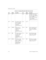
The SPARE pushbutton applies an active-Low signal to the XC3020A
on pin 16, and to the XC4003E on pin 18. You can isolate these pins
from the switch by using the trace-cut options on the solder side of
the board. The trace-cut options appear as point-to-point triangles;
the trace-cut option for the XC3020A is under its socket and the trace-
cut option for the XC4003E is under R3. The SPARE signal is pulled
High through a 27 kilohm resistor.
PROG Pushbutton (SW6)
The PROG pushbutton applies an active-Low signal to the DONE/
PROGRAM input on the XC3020A FPGA socket at pin 45 and to the
PROGRAM input on the XC4003E FPGA socket at pin 55. The PROG
signal is normally pulled High through a 13.5 kilohm resistor.
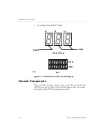
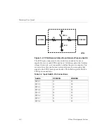
Eight General-Purpose Input Switches (SW3)
Eight switches connect to eight general-purpose inputs on both the
XC3020A and the XC4003E FPGAs. These switches provide logic
input to the FPGAs. An FPGA input pin is set to a logic "1" when a
switch is on, and a logic "0" when a switch is off. See the following
figure for a diagram.

