10GBASE-KR Ethernet TRD
20
UG1058 (v2017.1) April 19, 2017
Chapter 3:
Bringing Up the Design
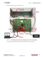
3. Connect the SMA cables on the Bulls Eye connector to the Tyco backplane as shown in
.
4. SMA cable 19 is REFCLK0_C_P and cable 20 is REFCLK0_C_N. Connect cable 19 and cable
20 from J41 to the clock out pins of Oscillator Si5368 on the Superclock module.
Connect cable 19 and cable 20 from J42 to the clock out pins of Oscillator Si570 on the
Superclock module.
5. Connect the power supply to the KCU1250 board.
6. Connect one end of the Micro-USB cable to USB-UART port (J1) and the other to the
Control PC.
7. Connect one end of the Micro-USB cable to USB-JTAG port (U80) and the other to the
Control PC.
X-Ref Target - Figure 3-1
Figure 3-1:
SMA Connections to the Backplane
COL6
COUNTER
BORED
COL6
COUNTER
BORED
Trace Length 16"
TYCO BACKPLANE
RX0_P
– SMA
17
TX0_P
– SMA
15
TX0_N – SMA
16
RX0_N – SMA
18
J41
GT X0Y8
Bank 226
TX0_P
– SMA
15
RX0_P
– SMA
17
RX0_N – SMA
18
TX0_N – SMA
16
J42
GT X0Y12
Bank 227
Transmit
Receive
X18441-120716


