background image

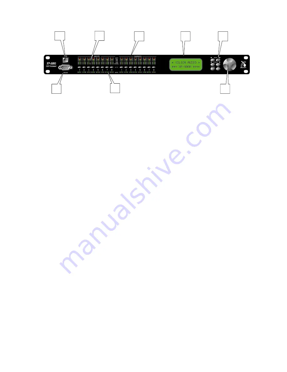
Front Panel Function

1. USB –a standard Type B USB connector. Device driver from the provided software CD

must be installed prior to usage.

2. RS232 – a standard female DB9 socket. A straight through cable is required for PC

connection.

3. Mute (Channel Menu) Buttons – Mute or un-mute input and output channels. When an

input channel is muted, a red LED will come on for indication.

When the <<Menu or Menu>> key is held down, the Mute Buttons se lects the
corresponding channel for the LCD menu display and is acknowledged by a green LED
below the button. The last modified menu will be displayed on the LCD.

Multiple

channels can be linked or unlinked by pushing the desired channels. This eases
programming for same parameters across multiple channels. Multiple Inputs can be
linked together and multiple outputs can be linked together. Inputs and Outputs are
linked separately.

4. Channel Menu LED – Indicates the activated channels for data modification.

5. Peak Level LED – Indicates the current peak level of the Signal:

Signal, -12dB, -6dB, -3dB, Over/Limit. The Input Limit LED references to the device's
maximum headroom. The Output Limit LED references to the threshold of the output
limiter.

6. LCD – Shows all the necessary information to control the unit.

7. Menu Buttons – There are 6 menu keys: <<Menu (Menu Down), Menu>> (Menu Up),

<<Cursor (Cursor Down), Cursor>> (Cursor Up), Enter/Sys/Speed, Exit.

The

functions of each key is explained below:

<<Menu:

Go to previous menu screen.

Holding this button down while

pressing Mute key will go to the specify channel menu.

Menu>>:

Go to next menu screen.

Holding this button down while pressing

Mute key will go to the specify channel menu.

<<Cursor:

Go to previous cursor in the menu screen.

Cursor>>:

Go to next cursor in the menu screen.

Enter/Sys/Speed: Enter is used only in the System Menu to proceed with selected

actions.

5

7

8

6

2

1

4

3

Summary of Contents for XP Series

Page 1: ...XP Series Loudspeaker Management System QUICK START GUIDE XILICA Audio Design...

Page 2: ...XP XP XP PC XP LCD 2 X 3 ENTER Recall Store Config 2 3 4 Copy General Secure Enter Menu Cursor Menu Control LED Menu Control Mute Menu Cursor Level 15 40 db Cursor 0 1300 ms Menu Control EQ 1 8...

Page 3: ...3 100ms RELEASE 200ms 3200ms Menu ON OFF Menu Name A Z Enter Enter Menu Store 30 Cursor 12 Enter 2 XP LEVEL Menu Control Level POL Menu Control Cursor 180 DELAY Menu Control Cursor Cursor 0 1300ms EQ1...

Page 4: ...nu Menu Cursor On Off Name Menu 5 Menu Control Menu Menu Menu Menu Menu Cursor Recall Enter Store Enter Menu 2 3 4 Config Enter Menu Menu None Stereo 2 way Stereo 3 way Stereo 4 way Copy Enter Menu Me...

Page 5: ...Menu Menu Menu Menu Secure PASSWORD Enter Enter 2 XP PC XP PC Menu Control Speed Speed Xilica China Unit 14 10 F Kwai Cheong Centre 50 Kwai Cheong Road Kwai Chung Hong Kong 50 10 14 Tel 852 2604 9382...

Page 6: ...gether Inputs and Outputs are linked separately 4 Channel Menu LED Indicates the activated channels for data modification 5 Peak Level LED Indicates the current peak level of the Signal Signal 12dB 6d...

Page 7: ...uttons are lit for the linked channels Any modification of the data for the selected channel will be applied to the linked channels as well To cancel the linking simply deselect the desired channel wh...

Page 8: ...steps Input Graphic Equalizer GEQ The graphic equalizer has 31 bands of equalization from 20Hz to 20kHz This control selects one of the 31 available bands The frequency corresponding to each band is...

Page 9: ...s from 0 3 to 1ms in 0 1ms steps then ranges from 1 to 100ms in 1ms steps RELEASE The compressor release time can be set at 2X 4X 8X 16X or 32X the attack time RATIO The compressor ratio is the slope...

Page 10: ...ups A program can be stored using this menu The old program with the same program number will be replaced Once the program is stored in the flash memory it can be recalled at a later time even after p...

Reviews: