background image

Copyright © 2019 Xflight Technologies LLC, Florida, USA 

14 

Overall Layout 


Summary of Contents for AUTOPILOT / TRIM

Page 1: ...Xflight Technologies LLC AUTOPILOT TRIM User Installation Guide Version 3 4 Mini Pix Flight Controller July 2020 Xflighttech com ...

Page 2: ...g the pilot full manual control of the aircraft See Appendix A for details B Setup and Connection 1 Ensure the Display is firmly seated and connected via the HDMI connector 2 Connect the GPS antenna to the Flight Controller GPS 12C socket 3 Connect the Flight Controller micro USB Link to one of the Raspberry Pi AUTOPILOT USB sockets 4 Connect the 5v DC power supply to the Raspberry Pi AUTOPILOT mi...

Page 3: ...ntroller is also firmly seated used for logging C Installation Overview Additional details in section F 1 Mount the Flight Controller horizontally facing forward sitting on a padded or foam base to reduce vibration Adjustments for setting perfect level and for tail wheel aircraft will be covered later under section G Calibration 2 Mount the GPS antenna on the dash or somewhere with line of sight t...

Page 4: ...l be red if below 6 otherwise green A red cross will appear if the satellite count is less than 5 A flashing green light on the GPS antenna also indicates satellites have been acquired If the satellite count is zero you will need to restart 3 Make sure the Flight Controller remains stable during startup Once the AUTOPILOT has started it will lock in the current GPS location and use this as its Hom...

Page 5: ...TOPILOT OFF switches back to Manual flight mode setting all other automated modes OFF This also disables the Servo PWM signals stops flight logging 2 STABILIZATION Mode Wings Level ON OFF Seeks to maintain wings level Altitude pitch unaffected 3 CRUISE Mode Heading Altitude ON OFF Seeks to maintain current heading Target and current Altitude The minimum altitude is 500 feet AGL for this mode at th...

Page 6: ...ILOT Status This displays current Flight Controller status STANDBY ACTIVE current AUTOPILOT mode and if at Home location STANDBY Aircraft is on the ground ready for flight ACTIVE System is active and aircraft may already be in flight 11 GPS Altitude above mean sea level AMSL in feet continuously displayed regardless of mode 12 Groundspeed in miles per hour continuously displayed regardless of mode...

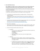
Page 7: ...or the AUTOPILOT is behind the instrument panel Make sure to leave sufficient room for the USB connections The rectangular cut out required will be approx 3 inches x 2 1 4 inches 76mm x 57mm Metal instrument panels will require an insulated layer between the touchscreen display surface and the panel for proper operation The plastic frame of the case provided makes for a good insulating layer Simpl...

Page 8: ...padded or foam base provided to reduce vibration and make sure it cannot move in flight The GPS antenna needs to be installed facing forward as it also has a built in compass and must have a good line of sight to the sky Satellite reception is good through glass plastic wood fabric etc but not through conducting surfaces such as metal The Flight Controller Mini Pix dimensions are 1 5 38mm square x...

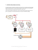
Page 9: ...separate switched and fused 5A circuit to the servo s circuit They need to be powered up at the same time The AUTOPILOT TRIM circuit always needs to be switched on before the servo s circuit The Trim switch wiring is also shown here There is a common ground wire and one wire each for pitch up pitch down roll up and roll down switches The wires are labelled accordingly ...

Page 10: ...rida USA 10 The Safety Enable will already be connected but for your reference this connects the AUTOPILOT Raspberry Pi pin 32 GPIO 12 signal and pin 30 Ground to the Flight Controller Mini Pix via the special cable provided opto isolator switch ...

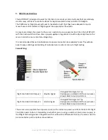
Page 11: ... to ensure minimal voltage drop It is recommended that each individual servo power connection be separately fused This will also assist in easy enabling and disabling of individual servos when it comes to flight testing Servo Wiring Flight Controller ESC Output 1 Elevator Signal Orange White Signal on Top Red power middle do NOT use cut wire Brown Black Ground on Bottom Flight Controller ESC Outpu...

Page 12: ...Copyright 2019 Xflight Technologies LLC Florida USA 12 Option 1 Xflight Servo Voltage Regulator Option 2 Xflight Servo Voltage Regulator with Differential Drivers ...

Page 13: ...or pitch and roll separately If you are planning to have more than one servo per axis e g for differential aileron movement then a Y cable will need to be used to split the signal to both servos It is recommended that shielded cable be used for the servo signal wiring with the shield connected to ground Differential drivers are strongly recommended for cable runs greater than 10 feet available fro...

Page 14: ...Copyright 2019 Xflight Technologies LLC Florida USA 14 Overall Layout ...

Page 15: ...is usually installed by default on the latest Windows OS It can be downloaded here https dotnet microsoft com download dotnet framework net462 3 Mission Planner installation Once you have downloaded the Mission Planner software double click the executable or msi file and install on your PC Allow the device driver to be installed by your operating system 4 Connect to the Flight Controller either by...

Page 16: ...eviously identified from the drop down box specify 115200 baud rate and hit CONNECT Once connected it will download the Flight Controller parameters and the connection icon will turn green c Once connected the Flight Controller parameters will be read and available to view modify the first time connecting will take longer as all the parameters are downloaded ...

Page 17: ...GHT DATA and you should see a properly leveled AHRS display These parameters can also be edited directly Use the top left navigation buttons and select CONFIG TUNING to view the parameters Then use the left option list to select Full Parameter Tree Under the AHRS section you will find the AHRS_TRIM parameters see screenshot These fine tune the AHRS to straight and level as the Flight Controller ma...

Page 18: ...nd level to the horizon as it would be flying AHRS_TRIM_X Roll angle tuning in radians positive to roll the AHRS reference plane left AHRS_TRIM_Y Pitch angle tuning in radians positive to pitch the AHRS reference plane down note 0 01 radians is approx 0 6 degrees If the Flight Controller needs to be installed in a different orientation than flat and pointing straight ahead this can be accommodated...

Page 19: ...S_OFS parameters see screenshot These can be manually modified to fine tune the compass heading Once you make a change be sure to click the Write Params button on the right to save the changes to the Flight Controller The Mission Planner heading display under Flight Data will update in real time as these parameters are written It is also advisable to take a backup copy of all parameters with Save ...

Page 20: ...buttons then follow the setup wizard prompts under Mandatory Hardware Select Compass then for a simple calibration select Pixhawk PX4 and follow the prompts Ensure the GPS antenna and Flight Controller are taped together when performing this and oriented in the same direction the GPS antenna has a built in compass For a more comprehensive calibration select Live Calibration and follow the prompts ...

Page 21: ...gies LLC Florida USA 21 Live Calibration Move the flight controller GPS antenna as directed Point North and rotate around pitch axis until level then turn 90 degrees and rotate around the roll axis until level hitting every white dot ...

Page 22: ...Copyright 2019 Xflight Technologies LLC Florida USA 22 Accelerometers Select Accel Calibration select the two calibration options and follow the prompts ...

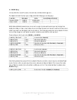
Page 23: ...s well as normal reverse direction of movement These setting can be found under SERVO1 and SERVO2 SERVO1_FUNCTION 19 Function 19 Elevator SERVO1_MAX 1900 Maximum deflection SERVO1_MIN 1100 Minimum deflection SERVO1_REVERSED 0 Direction of movement 0 Normal 1 Reversed SERVO1_TRIM 1500 Mid value Trim SERVO2_FUNCTION 4 Function 4 Aileron SERVO2_MAX 1900 Maximum deflection SERVO2_MIN 1100 Minimum defl...

Page 24: ...eyond the control surface hard stops You can define end points in the parameters above Ensure the servo torque rating is sufficient for the loads required There are resources on line to assist with this calculation Ensure you provide a regulated power source for the servos as specified by the manufacturer for maximum torque If your servos jitter and are constantly moving to remain stationary when ...

Page 25: ...ng static trim tabs may also be used to achieve this with the servo control surfaces trim tabs in a neutral position with the servos at their mid range values 1500 Ensure that calibration in section G has been completed It is recommended that you calibrate the TRIM System first and then the AUTOPILOT one axis at a time and make sure to keep a copy of the default parameter file before you begin as ...

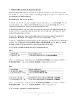
Page 26: ...h the AUTOPILOT into Manual flight mode You should see AP ON in green 4 Press the Servo Test Switch This will slowly move the pitch and roll servos from their neutral position to one of their endpoints as defined by SERVO1_MAX and SERVO2_MAX and back again As a safety precaution this switch only works when the groundspeed is less than 20mph You should see the control surfaces move in the following...

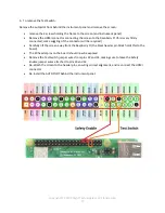
Page 27: ...y firmly connected some wiggling of the connector will be required Carefully lift the screen away from the Raspberry Pi the black header pin block holds this to the board The 40 header pins on the board should now be exposed Remove the Test Switch jumper wires from pins 33 and 34 making sure to leave the Safety Enable jumper wires attached to pins 30 and 32 Re attach the screen to the header pins ...

Page 28: ... few times or press continuously and make sure the elevator trim tab moves in the correct direction For a trim tab on a moveable elevator control surface this would be a downward movement of the trim tab allowing the airflow against the trim tab to push the elevator up Repeat for pitch down Action Control Surface Expected Movement Yoke switch pitch up Elevator Trim Tab Trim Tab Down Elevator up Yo...

Page 29: ...e current heading should not change much Immediately switch the AUTOPILOT off AP OFF or power down the roll servo s if you experience any adverse reaction 6 Put in a rapid bank angle for a couple of seconds and then release the yoke Do the same in the opposite direction You want the plane to roll out smoothly and gently with wings level on the new heading note this mode does not track a heading Im...

Page 30: ...V_P Roll Proportional gain default 2 RLL2SRV RLL2SRV_FF Roll Feed Forward gain default 2 If you get bank angle oscillation or overshoot then you will need to reduce RLL2SRV_P when back on the ground in increments of 0 1 11 You can also adjust the RLL2SRV_I response in steps of 0 1 to allow the aircraft to cope better with wind 12 If you see unexpected rapid servo movement then your PID gains may b...

Page 31: ...ch servo if you experience any adverse reaction 4 Wait a second or two then select CRUISE ON to enter Cruise mode Note the altitude 5 The current altitude should not change much Immediately switch the AUTOPILOT off AP OFF or power down the pitch servo if you experience any adverse reaction 6 Put in a gentle pitch angle for a couple of seconds to change altitude and then release the yoke Do the sam...

Page 32: ... to achieve smooth pitch reactions then recheck AHRS level configurations and or pitch axis orientation A more detailed explanation can be found here http ardupilot org plane docs roll pitch controller tuning html If all else fails then contact steve xflighttech com for support In Summary This table shows an overall general summary of the effect of raising PID gain values PID FF Parameter increasi...

Page 33: ...away from the airport 6 Return to Home Test Select HOME ON to enter RTL Return to Land mode The AUTOPILOT should now display the Home heading as the Target heading the Track is your actual heading and acquire this heading with a maximum bank angle of 20 degrees while maintaining current altitude Immediately switch the AUTOPILOT off AP OFF or power down the servos if you experience any adverse reac...

Page 34: ...modify parameters in flight If the aircraft turns too slowly then reduce NAVL1_PERIOD by 2 5 If it is weaving after a turn then increase NAVL1_PERIOD by 1 or 2 NAVL1 NAVL1_PERIOD NAV L1 Controller period seconds default 24 NAVL1 NAVL1_DAMPING NAV L1 Controller damping default 0 76 If you want the aircraft to smoothly acquire and maintain the loiter circle then set RTL_RADIUS to a larger number A g...

Page 35: ...r PASSWORD pixracer CHANNEL 11 ROUTER ADDRESS 192 168 4 1 PORT 14550 TYPE UDP 3 Once connected you will see the app download the flight parameters from the Flight Controller If you have problems connecting try one of these possible solutions a Ensure the Wi Fi module is connected to the TELEM1 port on the Mini Pix Flight Controller and that the Flight Controller is powered up b Restart the QGround...

Page 36: ...V ON indicating that the AUTOPILOT is now following the mission in AUTO flight mode and will navigate to the first waypoint Note that since the AUTOPILOT does not have control of the throttle if you have defined waypoints at different altitudes you will need to manually control power as appropriate to assist the AUTOPILOT in making altitude changes For an overview of the NAV function see https www...

Page 37: ...r box where you can download all or individual logs The Logs will be saved in your Mission Planner directory typically C users Your Name Documents Mission Planner logs FIXED_WING 1 Once loaded you can either review the logs within the Mission Planner graphing function Review a Log or view the flight path in Google Earth with the kmz and gpx files These files are automatically created To see the fl...

Page 38: ...ill NOT have the tlogs telemetry logs A more detailed description of the logs and graphing options is available here http ardupilot org plane docs common downloading and analyzing data logs in mission planner html Track and Elevation Profile speed altitude on Google Earth ...

Page 39: ...1 mile radius loiter circles above the HOME location There are 2 circles here with the autopilot maintaining very high precision orbits For a full description of all parameters please visit http ardupilot org plane docs parameters html But please note this includes all the ArduPlane parameters which are not all relevant ...

Page 40: ...party Flight Controllers in this application is contrary to Ardupilot s Code of Conduct for use in Manned Vehicles for more info see https firmware ardupilot org 4 INTELLECTUAL PROPERTY Intellectual property created made or originated by the officers employees or contractors of Seller shall remain the sole and exclusive property of Seller Any intellectual property associated with Goods specificall...

Page 41: ... and related equipment 8 INDEMNIFICATION Buyer shall defend indemnify and hold harmless Seller including its officers and agents from any and all actual or alleged claims demands causes of action liability loss damage and or injury to property or persons including without limitation wrongful death associated with the ownership and operation of the Goods of this contract This indemnity shall apply ...

Page 42: ...all be final and binding on the parties and judgment may be entered in conformity with the decision in any court having jurisdiction The agreement to arbitration shall be specifically enforceable under the prevailing arbitration law During the continuance of any arbitration proceeding the parties shall continue to perform their respective obligations under this Contract 11 NOTICE Any notice or com...

Page 43: ...r party to enforce any provision of this Contract shall not be construed as a waiver or limitation of that party s right to subsequently enforce and compel strict compliance with every provision of this Contract 16 APPLICABLE LAW This Contract shall be governed by the laws of the State of Florida in the USA ...

Page 44: ... or a portion of the Goods are non conforming Buyer may return the Goods to Seller at Buyer s expense Buyer agrees to securely mail the goods back to buyer with electronic tracking to the address listed above 19 PAYMENT Payment due shall be made to Xflight Technologies LLC by cash bank transfer credit card or PayPal prior to shipment of Goods If an invoice is not paid when due seller will not ship...

Reviews: