background image


OSKER User Manual Version 3.0 


18 

The OSKER

’s Timers


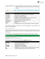
Timer Types 

SBD 

The  OSKER  will  communicate  with  the  Iridium  Gateway  based  on  this  interval.  If  the  OSKER 
successfully registers with the Iridium Satellite Constellation, it will send any messages queued 
for  transmission.  Once  this  is  finished  and  the  queued  outgoing  messages  have  been 
implemented, the OSKER will receive any queued commands from the Iridium Gateway. 

GPS 

The OSKER will communicate with the GPS network and get a location fix based on this interval. 
Any successful GPS fixes will be queued for the next Iridium transmission. 

The OSKER’s 

real-time 

clock will also be set and adjusted based on the GPS network. The GPS interval will execute before 
the SBD interval if they are scheduled for the same time. 

OSKER Timer Modes 

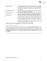
Start-up Mode 

Start-up mode (Timer 1)

 will begin when the OSKER is turned on via magnet removal, or if the 

OSKER is reset by an SBD command. This mode will last for one hour, after which the OSKER will 
enter 

Normal mode.


Normal Mode 

Once Start-up mode has finished, the OSKER will enter 

Normal mode (Timer 0)

. This is the default 

timer mode of the OSKER and will be used if no other modes apply. At default settings, the OSKER 
will transmit 1 GPS fix every 10 minutes. If no other modes are engaged, the OSKER will continue 
in normal mode until its batteries are depleted or the unit powered off. 

Alarm Mode 

If a watch circle has been set, the OSKER will enter 

Alarm Mode (Timer 2) 

when it exits the set 

radius or when the device detects it has been inverted on its GPS interval (if enabled).  


While in watch circle alarm mode, the OSKER will send information pertaining to the Watch Circle 
with each message, such as distance from centre and the duration in minutes that the device has 
been in that mode. 
If the device enters Alarm Mode due to inversion, the device will send an Orientation Change 
Message (see Stats message) at each point that it has changed its antenna used for transmission. 

No-GPS-Fix Mode 

If  the  OSKER  is  unable  to  get  a  GPS fix  after  repeated  attempts,  it  will  transmit a  GPS  Failure 
message and move to this timer mode 

(Timer 4)

.  


Summary of Contents for OSKER

Page 1: ...OSKER User Manual IRIDIUM GPS SURFACE TRACKING SYSTEM Version 3 0 March 2019...

Page 2: ...or your device contact support xeostech com Version History Version No Date Description 1 0 Nov 2015 Initial document 2 0 Jun 2017 Updated magnet switch details 2 1 Apr 2018 Re formatting standardized...

Page 3: ...8 OSKER Operation 9 Using the Magnets 9 Messages From the OSKER 10 Version Type V 10 Position Message 10 Compressed Binary Position 10 ASCII Position Type P 11 Status Change Message Type S 12 Informat...

Page 4: ...he Timer Command 19 Changing the Timers 20 Watch Circle 21 Enabling the Watch Circle 21 Setting the Watch Circle 21 Example 21 Enable Inversion Events 22 Message Enable 22 Other Commands 23 Installati...

Page 5: ...ing currents oil spills or other phenomenon Users can set the Watch Circle with a radius of up to 15km to get automatic notification if any of the units travel outside of a designated area See www xeo...

Page 6: ...ve 5 unique email addresses this may vary between service providers When registering an IMEI number please provide the service provider with a temporary Xeos testing account email address This account...

Page 7: ...ill always have the IMEI of the device in the subject line regardless of its name on XeosOnline FIGURE 2 AN EXAMPLE OF A RAW IRIDIUM MESSAGE FROM A DEVICE VIA EMAIL sbdservice sbd iridium com All mess...

Page 8: ...ng the Lat Long that the body has supplied Iridium is 80 confident always 80 that the device sending the message is within a circle 2 kilometers in radius with the Lat Long given as the centre of that...

Page 9: ...minimum of 1500 messages to a full deployment battery depletion Using the Magnets A magnetic tab embedded into the side of the OSKER s enclosure keeps the device s power source disengaged from the ele...

Page 10: ...used in OSKER Position Message Typical position messages are sent in compressed binary format Message Type 10 to save on data usage and are parsed in XeosOnline If XeosOnline is not used GPS Text Shor...

Page 11: ...S Fix higher is better 37 is good Each compressed message is 26 bytes in size with an additional 11 bytes added for each additional stacked position ASCII Position Type P In ASCII position format only...

Page 12: ...other factor the follow up Iridium session will send a synopsis of the latest statistics from the device This message will always be in ASCII format regardless of message format settings and approxima...

Page 13: ...icate with the Iridium network commands will remain queued for five days Command Format CREATING THE FILE To create an SBD command open a new file in a text editor ex Notepad and save it using the sbd...

Page 14: ...added at the beginning of the message The unlock code will only be changed if the firmware is updated or if commanded via unlock XXXXX YYYYY Where XXXXX is the current code and YYYYY is the new code...

Page 15: ...ver to the right hand target list using the button Type your command s into the command box and press send Remember to include the dollar sign ahead of each command and enter each command on a separat...

Page 16: ...ry delay in seconds gFRst 50 Number of GPS failures for GPS reset wcIC 85 WC Inner Percent for WC Warning message Val of WC Radius gBL 24 Maximum saved GPS fixes gFQ 12 Maximum GPS fixes per message S...

Page 17: ...ridium Message Count The number of SBD messages queued for sending Iridium Session Count Total successful Iridium connections Iridium On Time Total successful Iridium connections on first try Iridium...

Page 18: ...after which the OSKER will enter Normal mode Normal Mode Once Start up mode has finished the OSKER will enter Normal mode Timer 0 This is the default timer mode of the OSKER and will be used if no oth...

Page 19: ...powered on or reset Timer 2 Alarm Used once the unit s watch circle is triggered Timer 4 No GPS Fix Used when the GPS module consistently fails to acquire a fix While the timers are able to be manipu...

Page 20: ...uts a practical limit on the ratio of GPS fixes to Iridium checks Regardless the method being used to communicate with the OSKER timer commands are always the same format timer SYSTEM TIMER MODE INTER...

Page 21: ...nabled the specifics of the user s circle can be implemented Setting the Watch Circle The watch circle parameters can be set by sending the setcircle command using this format setcircle Latitude Longi...

Page 22: ...y messages These message formats can be changed using the msgenable command The OSKER has the following message types available for use Message Number Message Type 0 GPS Plain Text Short 1 GPS Plain T...

Page 23: ...for the OSKER btpcycle Power cycle Bluetooth batt Show battery status settings Show all settings stats Show statistics since last powerup reset statsL Show Lifetime Statistics switch X 1 0 Switch com...

Page 24: ...ice has two GPS Iridium antenna assemblies for such events Due to this the device can be deployed inverted as well as label side up Finally most use cases will require deployment from the sea or air T...

Page 25: ...lkaline Sleep Current 100uA avg Iridium Transmit 36mA 30s avg GPS Acquisition 15 mA 30s avg Voltage 12 0 Volts nominal Capacity 2 4 Amp Hours Electronics Digital Controller Xeos IRDC 3 GPS Receiver 48...

Page 26: ...OSKER User Manual Version 3 0 26 Appendix B Engineering Diagrams...

Page 27: ...ields are not used in the OSKER GPS Text Long Readout 12251850 Date and Time MMDDHHMM S Status Type message 2019 12 25 18 50 13 Date and time adds year and second of fix 44 71441 Latitude 63 60495 Lon...

Page 28: ...Warranty is void if failure of the product has resulted from accident abuse or misapplication Any replacement product will be warranted for the remainder of the original warranty period or ninety 90...

Reviews: