background image

INDEX

TECHNICAL 

DATA        3

REQUIREMENTS 

        4

INSTALLATION 

        5

FRAME 

SIZE 

         6

ELECTRICITY         7
VENTILATION 

        8


FRONT 

WALL 

        9 


FINISHING 

THE 

WALL 


       10

MOUNTING AIR FLOW BRACKETS TO ALUMINIUM FRAME  

11

BRACKET 

ALUMINIUM 

PROFILE 

     12

SEALING 

WALL 

AND 

FRAME 

      13

MOUNTING 

ALUMINIUM 

FRAME 

     14

MOUNTING 

AIR 

SLEEVES 

      14

PREPARATIONS FOR INSTALLATION DONE 


15

MOUNTING 

THE 

UNIT 

       15

CONNECTING ELECTRICITY AND PE CABLE 


16

MOUNTING 

THE 

UV-LAMPS 

      16

MOUNTING 

THE 

GLASS 

PANEL 

     17

TEST 

OF 

DEVICE 

        18

TROUBLE 

SHOOTING 

GUIDE 

      19

Note: this installation manual goes along with the user manual. Make sure to 

always hand over both manuals to the end user. 

Summary of Contents for Xiomara Feel Good V4

Page 1: ...INSTALLATION MANUAL FEEL GOOD SHOWER V4 FSHAND20201123...

Page 2: ...LE 12 SEALINGWALL AND FRAME 13 MOUNTING ALUMINIUM FRAME 14 MOUNTING AIR SLEEVES 14 PREPARATIONS FOR INSTALLATION DONE 15 MOUNTING THE UNIT 15 CONNECTING ELECTRICITY AND PE CABLE 16 MOUNTING THE UV LAM...

Page 3: ...01 Model Feelgood shower UV IR V4 Wit Xiomara Wellness www xiomarainfrared com Tussendiepen 76 9206 AE Drachten X I O M A R A Batchnummer 20453 Serienummer 001 Model Type Feelgood shower UV IR V4 Powe...

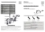
Page 4: ...STALLATION GUIDE FEELGOOD SHOWER UV IR V4 REQUIREMENTS SUPPLIED IN BOX SUPPLIED NOT SUPPLIED Glasplaat Frame Unit Aansluitlaatbeugel lucht boven Aansluitlaatbeugel lucht onder Aansluitlaatplaat luchtp...

Page 5: ...nternational IEC 60364 7 701 The Feelgood shower UV IR is an approved quality product and meets the CE guidelines For the correct operation of this product the user manual must be adhered The Feelgood...

Page 6: ...6 INSTALLATION GUIDE FEELGOOD SHOWER UV IR V4 2 FRAME SIZE Frame size 1828 x 376 mm 376 Minimum height 74mm to floor...

Page 7: ...DE FEELGOOD SHOWER UV IR V4 3 ELECTRICITY A Ym Vk min 2 5 mm2 230V 50Hz 16A L brown N blue yellow green B 6mm PE cable A B Feelgood shower should be connected to a seperate end group with a ground fau...

Page 8: ...utdoor bathroom itself one way valve s are required preventing moist air to penetrate into the device The device requires non condensing air When the air to the device is abstraced from a dry area clo...

Page 9: ...9 INSTALLATION GUIDE FEELGOOD SHOWER UV IR V4 5 FRONTWALL The construction must be able to support at least 50 kg Minimum height 74mm to floor...

Page 10: ...10 INSTALLATION GUIDE FEELGOOD SHOWER UV IR V4 6 FINISHING THEWALL 1 Wall construction 2 Plasterboard 3 Tiles 1 2 3 Tile and grout the wall or finish the wall to the chosen finish...

Page 11: ...nward Bottom bracket Fold the right corner inwards to attach to the left side Fold the left corner inwards to attach to the right side Screw the brackets to the aluminium frame with 4 screws each Loca...

Page 12: ...ON GUIDE FEELGOOD SHOWER UV IR V4 8 BRACKET ALUMINIUM PROFILE BEFORE MOUNTING THE ALUMINIUM PROFILE PLACE THE SAFETY BRACKET IN THE MIDDEL OF THE FRAME PREVENTING THE ALU FRAME TO WIDEN IN THE MIDDLE...

Page 13: ...V4 9 SEALING WALL AND FRAME Requirements 1 2 3 4 5 1 Wall 2 Plasterboard 3 Tile 4 Kit 5 Applying kit round the frame Rear view frame SEAL THE ALUMINUM FRAME ALL AROUND IN THE GROOVE INDICATED LOCATION...

Page 14: ...1 Screw the 2 screws in the side of the aluminium frame into the wooden construction of the hole Fold the four lips of the connection bracket over so that the ventilation tube is clamped Then place us...

Page 15: ...DONE 13 MOUNTING THE UNIT Pay attention Allow the sealant to harden well see the manual of the kit used We recommend a drying time of 24 hours Before continuing remove the safety bracket Place the un...

Page 16: ...ect the wires according below information L brown N blue yellow green Mount the 4 supplied UV lamps Xiomara 140 R 108 7 1 Be carefull with the ends of the UV lamps Pay attention The logo of the lamps...

Page 17: ...ANEL Click the connector into the pcb on the back side of the glass panel Mount the glass panel into the aluminium frame working from the bottom to the top Make sure the glass panel is aligned and all...

Page 18: ...ng the software version installed After 5 seconds the device should stop blincking and is ready for use Test the set up by pressing the UV button and IR button the device should switch on Test the fun...

Page 19: ...ce broke down Soluition switch off the relevant ground fault breaker and make sure the connector clicks into the mainboard and UI Make sure that there are no visible damages to the cable If the proble...

Page 20: ...XiomaraWellness Tussendiepen 76 9209 AE Drachten T 0512 51480 info xiomarainfrared com Xiomarainfrared com...

Reviews: