


3
Amplifiers & Preamplifiers
ZPR68-10
7. ZONE EXPANSION PORT. This port allows the ZPR68-10 to be linked with an EXP9 expansion
module to provide up to 15 zones of operation. The EXP9 includes 9 slots, allowing zone XCARDs
(PCB cards) to be added one by one in the field, or purchased already installed from the factory, for
zones 7 through 15.
8. ZONE OUTPUTS. The ZONE OUTPUTS consist of six sets of audio/video RCA type jacks - one set
for each zone. The L and R AUDIO jacks are connected to the appropriate Left & Right input jacks
on a main power amplifier for the zone and the VIDEO jack to the composite Video input on a zone
TV monitor or modulator. Any source connected to the SOURCE INPUTS can be switched to these
ZONE OUTPUTS when the zone receives an RC68+ INPUT command at the ZONE CONTROL - IR
INPUTS.
9. SOURCE INPUTS. The SOURCE INPUTS consist of eight sets of audio/video RCA type jacks - one
set for each input. The L and R AUDIO jacks and the VIDEO jack are connected to the corresponding
Left & Right audio and Video output jacks (where applicable) on up to eight source components
(satellite receivers, LD players, VCR's, AM/FM tuners, CD changers, etc.).
10. POWER SUPPLY Connector. 6-Pin DIN jack permits connection of a high current multi-voltage AC
power supply (included with each ZPR68-10).
11. CO Terminals. These two terminals provide a Control Output that goes high (+12 volts) when any zone
is first turned ON and goes low (0 volts) when the last zone is turned OFF. Use this control voltage
to drive the voltage sensing ports of power amplifiers, such as on the PA640 and the PA1235, and/
or AC power strips to provide power on/off for the common source components and/or to drive a total
system power on/off status indicator.
12. POWER Indicator LED. Indicates when power is applied to the ZPR68-10. It stays on continuously
even when all zones are turned off (as long as AC power is applied to the plug-in power supply).
13. COM PORT. This DB9 female connector permits 2-way communications with the ZPR68-10 using
custom designed control panels or computer programs. Port is RS-232 signal compatible, allowing
bidirectional data interface for status readout of ZPR68-10 settings as well as control of operational
functions.
COM PORT - RS232 Application Information. Use of this port requires proficiency in computer
programming and hardware interfacing. Refer to application Advisory, Volume 2, Number 1, for basic
communications protocol and hardware connection details. This advisory is available on Xantech's
web site at www.xantech.com/products/alist/htm. For more detailed information, including latest
updates, go to: http//www/xantech.com.engineerand make your selections from the list.
14. IR CONFIRM LED. Flashes when IR commands native to the ZPR68-10 are received & executed.
Won't flash when non-ZPR68-10 IR commands are passed through to operate source components,
etc.
15. Cover Panel. Remove this to access the 8 DIP
switches for setting the power level of the
COMMON IR OUTPUTS.
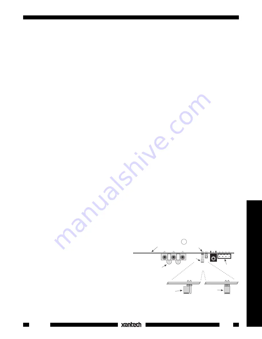
16. Video Gain Adjustment Jumpers (internal).
The video gain of each zone on the ZPR68-10
can be set to two levels, by the use of an
internal jumper. See Fig. 4 . With the jumper
on one pin only of PJ1, the video gain is unity
(0 dB). When the jumper is inserted onto both
pins of PJ1, the video gain is increased by +3
dB. You should use the +3 dB position only if
you notice a reduction in picture contrast and
brightness when running long cable lengths
(usually in excess of 150 feet). Since the majority of applications will not require additional gain, all
Zone Control
IR Input Jack
Zone A/V
Output Jacks
Video Gain
Adjustment Pins (PJ1)
Jumper
Zone PCB
Jumper
Shown in
0 dB Position
Jumper
Shown in
+3 dB Position
16
Fig. 4 Video Gain Adjustment - Jumper Locations


