


14
External IR Receiver Connections
Use an external Xantech IR Receiver in cases where a hand-held remote
needs to be pointed somewhere other than at the MRKP1 or in cases where
additional interference requires the use of a different type of IR receiver or IR
receiver mounting location. Typical IR Receiver locations are near a TV or other
equipment such as a Local Source (DVD Player, A/V Receiver,…etc.). A CAT-
5 cable can be used to extend the IR receiver’s wire, if necessary. Refer to the
bottom of the Specifications section (page 20) for wiring instruction when using
CAT-5 cable to extend the IR signal.
By default, the MRKP1 External and Internal IR receivers are both active.
Having both active, in some cases, can cause issues with IR signal reflection
and/or multiple processing of the same IR command. Therefore, in such
specific cases it is advisable to disable the Internal IR when using an external
IR receiver
(Internal IR can be disabled by removing jumper clip on item #2 of
Figure 2.3)
.
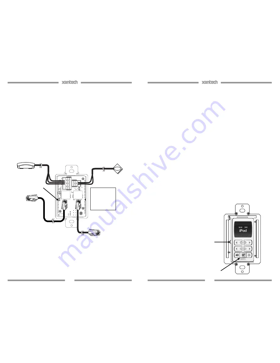
Figure 3.2: MRKP1 to External IR Connections
Xantech External IR
receiver
To MRC88 Zone Port
Internal IR Receiver
Enable/Disable
Xantech IR
Emitter
To Expansion keypad
Note:
See
Polarity markings
near connecting
block for proper
wiring of IR
receiver and IR
emitter
15
4. MRKP1 Main Setup Menu
To access the Main Setup Menu,
1. Press and hold down the “
X
”
key for at least 3 seconds.
2. Once the Main Setup Menu is displayed on the screen
,
use the
“SOURCE
<
” and “SOURCE
>
” buttons to highlight the category to be
changed.
3. Press the “
X
” button to choose the category.
4. Use the “SOURCE
<
” and “SOURCE
>
” buttons to highlight the
parameter to be changed.
5. Use the “VOLUME UP” and “VOLUME DN” buttons to change the
parameters. (For further details see diagram on Figure 4.1)
The Main Setup Menu consists of the following categories:
KP INFO
- displays information about the unit (Model number, Keypad
Address, and Version number)
USER SETUP
– allows adjustments of BALANCE, BASS, TREBLE, and
BACKLIGHT Color.
INST SETUP
– Allows installer to configure the unit for initial setup and
other options.
NOTE: The
INST SETUP
category can only be accessed
by pressing the hidden
“
SETUP
”
button and the
“
X
”
button at the same
time. A Q-tip with cotton tip removed, or similar, is recommended for use
when pressing this hidden switch (see Figure 4.0 below)
EXIT
– Leave the Main Setup Menu and go back to normal display mode.
Figure 4.0: Trim plate removed showing
SETUP Button location
SETUP
button
X
button


