

2
791-44
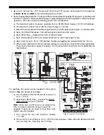
2. Be sure to connect the +12V, Output and Gnd of each IR receiver and keypad to the respective
+12VDC, IR IN and GND of the connecting block as shown.
3. Power Supply Requirements. You may combine many Xantech keypads, IR receivers, controllers and
emitters in a system. Having sufficient power supply voltage and current available is critical for proper
operation. Be sure to take the following factors into consideration:
a) The maximum current for proper operation from a 781RG Power Supply is 120 mA (milliamps).
b) The maximum current from a 782-00 Power Supply is 1000 mA.
c) Most IR receivers draw 2 mA without signal and 10 mA with signal (check specs. on actual model).
d) Each 730 Smart Pad draws 7 mA without signal and 65 mA with signal.
e) Each Smart Pad
2 or 3
draws 85 mA with or without signal.
f) Each emitter draws 3 mA in low power mode and 12 mA in high power mode.
g) Add 10 mA for each 794 or 797 Interface module used, if they are powered from the 791-44.
h) When using combinations of these devices, add up the currents as shown in the following example.
Then choose the power supply or supplies. Do not exceed their maximum current capabilities as
noted above!
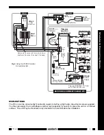
For example, the power supply needed for the system
shown in Fig. 2 is arrived at as follows:
a) The no signal current for the five IR receivers is
5 x 2 = 10 mA.
b) Assuming a Smart Pad
2 or 3
keypad, the with or
without signal current is = 85 mA.
Note: Since only one IR source can operate at a
time, the lower current IR receivers (and 730
keypads if used) do not need to have their "with
signal" currents included.
c) The current for one 794 Interface module
= 10 mA.
d) The current for six emitters is 6 x 3 = 18 mA (in the low power mode. Also the 286 dual emitters
count as only one, since they are in series).
OUT
+12V
IR IN
GND1
GND2
+12V
1 (ON)
0 (OFF)
1 2 3 4 5 6 7 8 910
ON
SENDER/
EMITTER
123456789
1
0
ROOM 4
OUT
V
IR
RCVR
PWR
GS
291-10
Hidden Link™
IR Receiver
GND
+12V
7 Foot Quick
Connect Cable
CB12
Connecting Block
X
To 120 VAC
(unswitched)
781RG
Power
Supply
791-44
Amplified
Connecting Block
Satellite Receiver
AV Receiver
VCR
MAIN ROOM, EQUIPMENT CABINET, ETC.
282M
Mouse Emitter
282M
Emitter
283M
Blink-IR™
7 Foot 3-Conductor
Cable with Quick
Connect Stereo Mini Plug
490-30
Series
Micro Link™
IR Receivers
GND
+12V
ROOM 3
780-10
J-Box
IR Receiver
490-00
Series
Micro Link™
IR Receivers
3-Wire
Cable
GND
+12V
480-00
Dinky Link™
IR Receiver
Red
Stripe
GND
IR OUT
+12V
ROOM 2
ROOM 1
286M
Dual Blink-IR™
3-Wire
Cable
IR OUT
GND
+12V
Red
Stripe
+12V
IR OUT
GND
780-10
J-BOX RECEIVER
XANTECH
CAUTION:
See text, item 5.
CD Changer
Cassette DecK
Laser Disc
283M
Blink-IR™
Makita
Drape Controller
Dimmer Control
794-60
Universal
Interface
286M
Dual Blink-IR™
282M
Mouse Emitter
794
UNIVERSAL INTERF
ACE
GND
Smart
Pad
2 or 3
ST
See
Item 4
below
+12 VDC
+ 1 2 V D C
G N D
EMITTERS
12 VDC
HIGH
IR
OUT
S TAT U S
I R I N
IR
RCVR
791-
44
AMPLIFIED
CONNECTING BLOCK
®
IR OUT
IR OUT
IR OUT
XANTECH
Fig. 2
A typical 791-44 System


