


Warning for internal battery pack
To reduce risk of fire or burns:
1.
Do not attempt to open, disassemble, or service the battery pack.
2.
Do not crush, puncture, short external contacts, or dispose of in fire or water.
3.
Do not heat above 60
o
C
9.
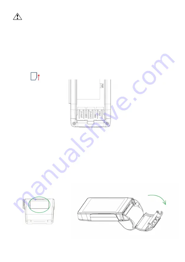
I
NSERT
SAM/SIM
CARD
After removing the battery, the user can find SAM*2 (left) slots and SIM*1(right) slot at the
bottom side of device. Please insert the card correctly as the icon shown on the cover as Figure
12:
Figure 12
10.
L
OADING
T
HE
P
APER
Gently pop the printer cover’s latch; then pull the cover (Figure 13). Load a roll of thermal
paper into the printer. Load it so that the print-side of the paper will feed out facing the
operator. Close the cover by pressing on the center of the printer cover. Use the serrated bar
to tear off any excess paper.
Figure 13


