X10 VK49A Owner'S Manual Download Page 6

11

10

S

ETTING


UP


THE

 C

AMERA

/V

IDEO

 S

ENDER

AND

 R

EMOTE

C

ONTROLLED

 P

OWER

 S

UPPLY

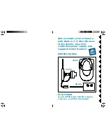
Referring to the diagrams below and on the next page:

1. Attach the camera to a wall using the screws provided.

2. If you install the camera outdoors, make a small hole in your

exterior wall and pass the low voltage power jack through it.

3. Plug the XM10A's power supply jack into the socket on the

adapter cable from the camera.

4. Plug the power supply into any 120V AC outlet.

5. Set the channel switch on the camera to any letter A, B, C, or D

6. Adjust the antenna if necessary to aim it in the direction of the TV

or monitor that you will view the camera on.

7. Set the Housecode dial to a letter between A

and P that matches the Housecode dial on the
X10 remote controls you want to use it with. Set
the Unit Code dial to a number between 1 and
16. This lets you turn the camera connected to
the XM10A on and off by remote control (using
X10 remote controls, sold separately). See the
owner's manual supplied with X10 remote
controls for more details.
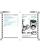
C

ONNECTING

 U

P

2.4 GHz Video
Antenna

Plug power
supply in here.

Important: 

Unplug

power supply before
unplugging power jack.

Plug into
any AC
outlet

Set channel switch to
match setting on
Video Receiver.

Outdoors

Indoors

Attach camera to a
wall, indoors or
outdoors.

Set codes
wheels.

Summary of Contents for VK49A

Page 1: ...r Color Camera with Built in 2 4 GHz Wireless Video Sender plus X10 controlled power supply and separate Video Receiver MODEL VK49A INCLUDES XC10A CAMERA XM10A ADDRESSABLE POWER SUPPLY AND VR31A VIDEO...

Page 2: ...n to overturn 10 Ventilation Slots and openings in the cabinet are provided for ventilation and to ensure reliable operation of the product and to protect if from overheating and these openings must n...

Page 3: ...ions NOTE Modifications to this product will void the user s authority to operate this equipment 11 Power Sources This product should be operated only from the type of power source indicated on the ma...

Page 4: ...VIDEO RECEIVER 9 CONNECTING UP 10 SETTING UP THE REMOTE CONTROLLED POWER SUPPLY 10 SETTING UP THE CAMERA VIDEO SENDER 11 SETTING UP THE VIDEO RECEIVER 12 FINE TUNING YOUR SYSTEM 14 WARRANTY 15 Power...

Page 5: ...r A V Jacks Power Supply Jack 2 4 GHz Channel Switch on bottom TV Channel Switch on bottom ON OFF Switch on side 2 4 GHz Video Antenna CONTROLS AND CONNECTIONS CAMERA VIDEO SENDER VIDEO RECEIVER Set c...

Page 6: ...to aim it in the direction of the TV or monitor that you will view the camera on 7 Set the Housecode dial to a letter between A and P that matches the Housecode dial on the X10 remote controls you wa...

Page 7: ...ll outlet 3 Turn the Video Receiver s power switch on side of unit on 4 Set the channel switch to the same letter as you set on the camera A B C or D 5 Position the Video Receiver in a convenient loca...

Page 8: ...LIMITATIONS ON HOW LONG AN IMPLIED WARRANTY LASTS AND OR THE EXCLUSION OR LIMITATION OF INCIDENTAL OR CONSEQUENTIAL DAMAGES SO THE ABOVE LIMITATIONS AND EXCLUSIONS MAY NOT APPLY TO THE ORIGINAL CUSTOM...

Page 9: ...16 X10 USA Inc 3824 North 5th St Suite C North Las Vegas NV 89030 Web Site www x10 com VK49A 03 99...

Reviews: