


14
Technical support: [email protected] EMEA/ROW: +44 (0) 1793 230 343
US/CAN/MEX: +1-518-289-1294 Toll Free Technical Support: +1-844-280-WYRE (9973)
ADV
ANCED OPERA
TION
4
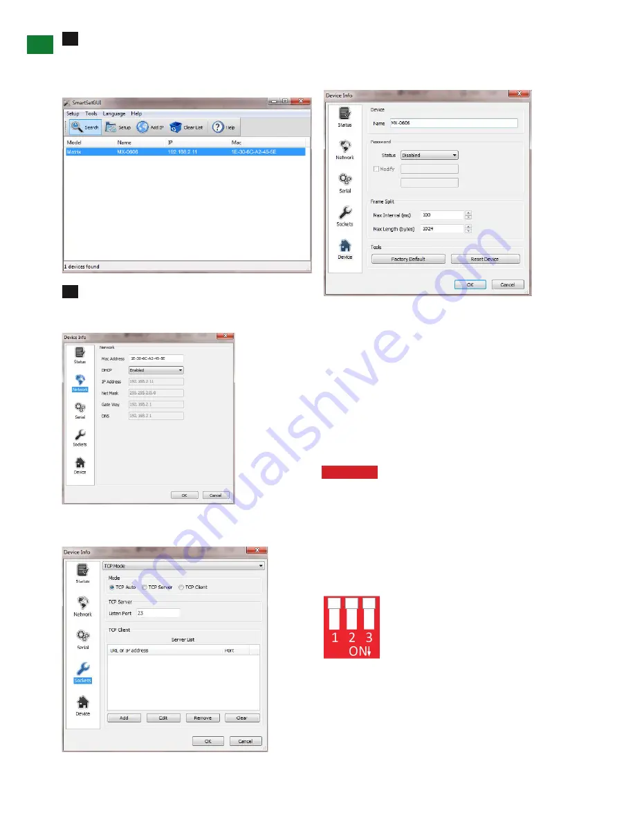
If you do not initially see your matrix being
connected, click on the SEARCH button
a. If it is recognized, it may show up as the default Matrix
8:8 setting rather than MX-0404-PP-KIT
Select the matrix and click on SET-UP. From here
you can change settings on the network card
- Network: Enable DHCP to set a static IP, etc.
Sockets:
Drivers are built around the use of Port 23. If
you see that the Port is set to 1984, change to Port 23
Device: change name of matrix
If the default setting reflects an 8x8 matrix model, use this
page to manually change name of your matrix to better
reflect the model you have.
iv. EDID DIP Switch setting
Distribution of HD signals through the matrix requires
mutual communication or ‘handshake’ between source
and display. If there is any disparity between the two,
successful transmission becomes problematic.
This matrix comes equipped with an EDID DIP switch
for manual adjustment of matrix settings to encourage
communication between INPUT and OUTPUT devices. If
installation compatibility issues arise, check the settings
on your connected devices and adjust the DIP settings as
required.
Attention
Changes to the DIP switch settings
should be made with the matrix OFF, ideally with
all power cables and HDMI leads and UTP cables
removed to guard against electrostatic build up that
may damage your system. DO NOT HOTSWAP your
cables when changing DIP SETTINGS.
ALL changes to the DIP settings become effective
upon powering ON the matrix.
EDID Copy from Output display to Input
port (Force Signal Output mode)
To copy the EDID from an OUTPUT display
to a specific INPUT port, first set the DIP
switch to this position. Then select the INPUT by pressing
and holding the chosen OUTPUT SELECT button for 3
seconds for the EDID to be copied from the DISPLAY to
the INPUT port.
3


