background image

WIRELESS CONNECTIVITY & SENSORS

User manual Setebos-I

9 Design in guide

9.1 Advice for schematic and layout

For users with less RF experience it is advisable to closely copy the relating evaluation board
with respect to schematic and layout, as it is a proven design. The layout should be conducted
with particular care, because even small deficiencies could affect the radio performance and
its range or even the conformity.
The following general advice should be taken into consideration:

• A clean, stable power supply is strongly recommended. Interference, especially oscilla-

tion can severely restrain range and conformity.

• Variations in voltage level should be avoided.

• LDOs, properly designed in, usually deliver a proper regulated voltage.

• Blocking capacitors and a ferrite bead in the power supply line can be included to filter

and smoothen the supply voltage when necessary.

No fixed values can be recommended, as these depend on the circumstances
of the application (main power source, interferences etc.).

The use of an external reset IC should be considered if one of the following
points is relevant:

• The slew rate of the power supply exceeds the electrical specifications.

• The effect of different current consumptions on the voltage level of bat-

teries or voltage regulators should be considered. The module draws
higher currents in certain scenarios like start-up or radio transmit which
may lead to a voltage drop on the supply. A restart under such circum-
stances should be prevented by ensuring that the supply voltage does not
drop below the minimum specifications.

• Voltage levels below the minimum recommended voltage level may lead

to malfunction. The /Reset pin of the module shall be held on LOW logic
level whenever the VCC is not stable or below the minimum operating
Voltage.

• Special care must be taken in case of battery powered systems.

Order code 2611011024020

24

Version 1.1 , July 2022

www.we-online.com/wcs

Summary of Contents for 2611011024020

Page 1: ...USER MANUAL SETEBOS I 2611011024020 VERSION 1 1 JULY 1 2022 ...

Page 2: ...eet and user manual This is especially important for Wireless Connectivity products that were not purchased directly from Würth Elektronik eiSos A firmware update on these respective products may be required We strongly recommend to include in the customer system design the possibility for a firmware update of the product ...

Page 3: ...ry Manual version FW version HW version Notes Date 1 0 1 0 1 2 Initial release June 2021 1 1 1 1 1 2 Updated chapter Firmware history Added helpful application notes related to Setebos I July 2022 Order code 2611011024020 1 Version 1 1 July 2022 www we online com wcs ...

Page 4: ...II populated on motherboard with USB interface for test and evaluation purpose I O Input output Pinout description RF Radio frequency Describes wireless transmission UART Universal Asynchronous Receiver Transmitter Allows the serial communication with the module Order code 2611011024020 2 Version 1 1 July 2022 www we online com wcs ...

Page 5: ...na 19 4 2 2 External antenna 19 5 Functional description 20 6 Host connection 21 7 Firmware updates 22 8 Firmware history 23 9 Design in guide 24 9 1 Advice for schematic and layout 24 9 2 Dimensioning of the micro strip antenna line 26 9 3 Antenna solutions 27 9 3 1 Wire antenna 28 9 3 2 Chip antenna 28 9 3 3 PCB antenna 28 9 3 4 Antennas provided by Würth Elektronik eiSos 29 9 3 4 1 2600130021 H...

Page 6: ...oduct 49 16 4 Exemption clause 49 16 5 EU Declaration of conformity 50 16 6 FCC Compliance Statement 51 16 7 IC Compliance Statement 51 16 8 FCC and IC requirements to OEM integrators 51 16 8 1 Pre certified antennas 53 17 Important notes 54 17 1 General customer responsibility 54 17 2 Customer responsibility related to specific in particular safety relevant appli cations 54 17 3 Best care and att...

Page 7: ...19 2 Usage and obligations 58 19 3 Ownership 59 19 4 Firmware update s 59 19 5 Disclaimer of warranty 59 19 6 Limitation of liability 60 19 7 Applicable law and jurisdiction 60 19 8 Severability clause 60 19 9 Miscellaneous 60 Order code 2611011024020 5 Version 1 1 July 2022 www we online com wcs ...

Page 8: ...he corresponding Software Development Kit SDK for most commonly used host processors This SDK contains drivers and examples in C code to communicate with the corresponding radio module This application note shows which SDKs are available and describes how to download and use them Application note ANR009 Proteus III Advanced developer guide http www we online com ANR009 This advanced developer guid...

Page 9: ...duct containing Bluetooth technology needs to be listed at the Bluetooth SIG spe cial interest group This application explains the steps to be done to gain a Bluetooth listing for the end product using a Würth Elektronik eiSos Bluetooth LE radio module Application note ANR030 nRF Connect http www we online com ANR030 This application note gives a short overview about the options to create a custom...

Page 10: ...n selecting the Bluetooth LE standard the Setebos I acts as a Proteus III radio module When selecting the WE ProWare radio stack the Setebos I acts as a Thyone I radio module Depending on the selected standard the corresponding module s specifications apply These are available in the dedicated Proteus III 1 and Thyone I 2 user manuals Small dimensions 8 x 12 mm comparable to a nano sim card includ...

Page 11: ...ator ARM Cortex M4 Flash RAM 2 4GHz Radio core 50Ω port to λ 4 antenna external wiring according to trace design Antenna Figure 2 Block diagram of the module 1 2 Ordering information WE order code Description 2611011024020 Setebos I Module Tape Reel 2611129024021 Mini evaluation board for Setebos I Table 3 Ordering information Order code 2611011024020 9 Version 1 1 July 2022 www we online com wcs ...

Page 12: ...chip power on reset circuitry may not function properly for rise times longer than the specified maximum An instable supply voltage may significantly decrease the radio performance and stability 2 2 Absolute maximum ratings Description Min Typ Max Unit Supply voltage VDD 0 3 3 9 V Voltage on any digital pin VDD 3 6V 0 3 VDD 0 3 V Voltage on any digital pin VDD 3 6V 0 3 3 9 V Input RF level 10 dBm ...

Page 13: ...le TX or RX delay fast mode 40 µs Disable TX delay 6 µs Disable RX delay 0 µs Table 7 Timing and RSSI Description Typ Unit Output power conducted 6 dBm Output power integrated antenna 4 dBm Input sensitivity conducted BER 1E 3 1Mbps 92 dBm Input sensitivity integrated antenna BER 1E 3 1Mbps 90 dBm Table 8 Transmit and receive power All transmit and receive power levels are measured on the evaluati...

Page 14: ...or rate of 1 with a payload length of 38 byte at different data rates The PER 1 is a harder criteria resulting in 2 dBm less sensitivity Data rate kbit s Typ Unit 1000 PER 1 90 dBm 2000 PER 1 87 dBm 500 PER 1 94 dBm 125 PER 1 98 dBm Table 9 Sensitivity at different data rates Order code 2611011024020 12 Version 1 1 July 2022 www we online com wcs ...

Page 15: ... V output set low high drive VDD 2 7 V 6 10 15 mA Current at VSS 0 4 V output set low high drive VDD 1 7 V 3 mA Current at VDD 0 4 V output set high standard drive VCC 1 7V 1 2 4 mA Current at VDD 0 4 V output set high high drive VDD 2 7 V 6 9 14 mA Current at VDD 0 4 V output set high high drive VDD 1 7 V 3 mA Internal pull up resistance 11 13 16 kΩ Internal pull down resistance 11 13 16 kΩ Table...

Page 16: ...UP CTS RTS URXD UTXD LED_2 LED_1 BUSY MODE_1 B2 Figure 3 Pinout top view No µC Pin Designation I O Description 1 ANT I O RF connection to PCB antenna see sec tion 4 2 2 RF I O 50Ω RF connection through radio front end to transceiver part of chipset see section 4 2 Order code 2611011024020 14 Version 1 1 July 2022 www we online com wcs ...

Page 17: ...only Mode Trans parent Mode Do not connect if not needed 11 P0 00 XL12 LED_1 Output Indicates the module state active high Do not connect if not needed 12 P0 01 XL22 LED_2 Output Indicates the module state active high Do not connect if not needed 13 P1 08 UTXD Output UART Transmission 14 P1 09 URXD Input UART Reception Uses internal pull up resis tor1 15 P0 11 RTS Output RTS signal if flow control...

Page 18: ... remote GPIO access Do not connect if not needed B6 P0 07 B6 GPIO Pin for remote GPIO access Do not connect if not needed Table 11 Pinout 1 Internal pull ups or pull downs are configured at startup by the firmware installed in the SoC The pull up on the RESET pin cannot be disabled by firmware 2 Pins available to connect an external crystal in custom firmware The standard firmware of Setebos I doe...

Page 19: ...s UTXD URXD RTS CTS RESET ANT RF Host Controller Setebos I VDD 1 6 3 5 WAKE_UP BOOT MODE_1 BUSY LED_1 LED_2 7 8 4 SWDIO SWDCLK 9 VDD RPS 2 GND GND 1 Figure 4 Minimal pin connections The above image shows the steps to be performed to integrate the Setebos I into a custom end device 1 Supply voltage and ground Connect the VDD and GND pins to supply the radio module with power 2 Radio standard select...

Page 20: ... pin to the host controller to switch between command and peripheral only mode 8 Optional Status indication Connect the BUSY LED_1 and LED_2 pins to the host controller to allow easy indication of the status 9 Optional Flash and debug interface In case of custom firmware development it is recommended to additionally have the pins SWDIO and SWDCLK accessible in order to support a fail safe update o...

Page 21: ...nada please refer to the trace design in chapter 10 2 4 2 2 External antenna For applications that use an external antenna the Setebos I provides a 50 Ω RF signal on pin RF of the module In this configuration pin ANT of the module has to be connected to ground and pin RF to the external antenna via 50 Ω feed line Refer to chapter 10 for further information The use cases for the integrated antenna ...

Page 22: ...an be found in chapter 5 of the Proteus III user manual 1 A high level during and shortly after reset starts the WE ProWare firmware In this case the functional description of the Thyone I radio module applies This can be found in chapter 5 of the Thyone I user manual 2 Example That means when requesting the firmware version of the Setebos I by a UART command the radio module will return the firmw...

Page 23: ...MCU As a result of this the module can be designed in with most host controllers from a 8051 to the more advanced ARM core architecture Host Controller Setebos I UTXD URXD RTS CTS RTS CTS URXD UTXD Figure 5 Host Interface Depending on the selected standard Bluetooth Low Energy 5 1 or Proprietary the corre sponding characteristics apply These are available in the dedicated Proteus III 1 and Thyone ...

Page 24: ... their verified product even if the standard product is updated The Setebos I uses the OTAP over the air update procedure of the Proteus III radio mod ule The OTAP mode can be enabled using the BOOT pin or the respective Proteus III UART command For more details please refer to the Proteus III user manual 1 Please note that only Setebos I OTA firmware images can be loaded on the Setebos I Separate...

Page 25: ...ncludes Proteus III firmware version 1 3 0 Includes Thyone I firmware version 1 5 0 Version 1 1 0 Release Includes Proteus III firmware version 1 4 0 Includes Thyone I firmware version 1 6 0 For more details see Proteus III and Thyone I user manual Order code 2611011024020 23 Version 1 1 July 2022 www we online com wcs ...

Page 26: ... when necessary No fixed values can be recommended as these depend on the circumstances of the application main power source interferences etc The use of an external reset IC should be considered if one of the following points is relevant The slew rate of the power supply exceeds the electrical specifications The effect of different current consumptions on the voltage level of bat teries or voltag...

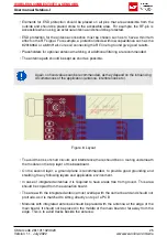
Page 27: ...he influencing circumstances of the application antenna interferences etc Figure 6 Layout To avoid the risk of short circuits and interference there should be no routing underneath the module on the top layer of the baseboard On the second layer a ground plane is recommended to provide good grounding and shielding to any following layers and application environment In case of integrated antennas i...

Page 28: ...t one separate through hole connection to the ground layer ESD protection elements should be placed as close as possible to the exposed areas Figure 7 Placement of the module with integrated antenna 9 2 Dimensioning of the micro strip antenna line The antenna track has to be designed as a 50Ω feed line The width W for a micro strip can be calculated using the following equation W 1 25 5 98 H e 50 ...

Page 29: ...erally a compromise between size and range Both usually fit inside a housing Range optimization in general is at the expense of space Antennas that are bigger in size so that they would probably not fit in a small housing are usually equipped with a RF connector A benefit of this connector may be to use it to lead the RF signal through a metal plate e g metal housing cabinet As a rule of thumb a m...

Page 30: ...3 2 Chip antenna There are many chip antennas from various manufacturers The benefit of a chip antenna is obviously the minimal space required and reasonable costs However this is often at the expense of range For the chip antennas reference designs should be followed as closely as possible because only in this constellation can the stated performance be achieved 9 3 3 PCB antenna PCB antenna desi...

Page 31: ...quency range GHz 2 4 2 5 Impedance Ω 50 VSWR 2 1 Polarization Linear Radiation Omni Directional Peak Gain dBi 2 8 Average Gain dBi 0 6 Efficiency 85 Dimensions L x d mm 83 1 x 10 Weight g 7 4 Connector SMA plug Operating temp C 40 80 Special care must be taken for FCC certification when using this external antenna to fulfil the requirement of permanently attached antenna or unique coupling for exa...

Page 32: ...an Conformity the evaluation board serves as reference design For the FCC the evaluation board serves as trace design chapter 10 2 that has to be followed when referencing the module FCC ID The certification runs on Proteus III and is valid for the Setebos I by a class 1 permissive change Order code 2611011024020 30 Version 1 1 July 2022 www we online com wcs ...

Page 33: ..._1 RPS B2 B3 B4 B5 B6 BUSY LED_1 LED_2 UTXD URXD RTS CTS WAKE_UP GND VDD VDD P0 00 LED_1 P0 00 LED_1 P0 01 LED_2 P0 01 LED_2 UTXD GND SWDIO SWDIO SWCLK SWCLK URXD P0 09 RPS P0 09 RPS P0 10 RSVD P0 10 RSVD P0 21 RSVD P0 22 BUSY P0 22 BUSY P0 23 RSVD P1 00 RSVD P0 07 RSVD P0 19 MODE_1 P0 19 MODE_1 P1 08 UTXD P1 08 UTXD P1 09 URXD P1 09 URXD P0 12 CTS P0 12 CTS P0 11 RTS P0 11 RTS RTS CTS P0 03 P0 18...

Page 34: ...4 4 CON3 B18 B18 B17 B17 B16 B16 B15 B15 B14 B14 B13 B13 B12 B12 B11 B11 B10 B10 B9 B9 B8 B8 B7 B7 B6 B6 B5 B5 B4 B4 B3 B3 B2 B2 B1 B1 B19 B19 B20 B20 B21 B21 B22 B22 B23 B23 B24 B24 B25 B25 B26 B26 B27 B27 B28 B28 B29 B29 B30 B30 B31 B31 B32 B32 1 2 3 P4 R14 R15 R16 R17 VDD VDD VDD VDD VDD VDD GND GND GND GND GND GND GND GND GND GND GND GND GND 3V 3V 5V0 5V0 D D D D SWDIO SWDIO SWCLK SWCLK 5V 5V ...

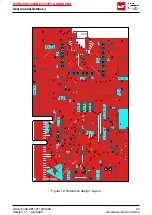
Page 35: ...WIRELESS CONNECTIVITY SENSORS User manual Setebos I 1 no metal antenna Q1 Figure 12 Reference design Layout Order code 2611011024020 33 Version 1 1 July 2022 www we online com wcs ...

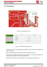
Page 36: ... under the module and antenna free area Second layer is filled with ground plane except the antenna free area Third layer is the supply layer except antenna free area Some routing is allowed not dividing the supply layer in to many or too small parts Bottom layer is used for routing and filled with ground except antenna free area Order code 2611011024020 34 Version 1 1 July 2022 www we online com ...

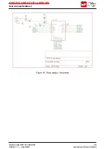
Page 37: ...WIRELESS CONNECTIVITY SENSORS User manual Setebos I Figure 15 Trace design Schematic Order code 2611011024020 35 Version 1 1 July 2022 www we online com wcs ...

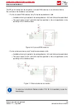
Page 38: ...all be specified in the end application corre sponding to the individual need Figure 16 On board PCB antenna For the external antenna 22 pF shall be assembled on C6 If additional tuning is needed in the end application C21 and C26 can be assembled The exact values of C21 and C26 shall be specified in the end application corre sponding to the individual need Figure 17 External antenna connection To...

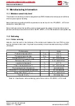
Page 39: ...tention must be paid on the thickness of the solder resist between the host PCB top side and the modules bottom side Only lead free assembly is recommended according to JEDEC J STD020 Profile feature Value Preheat temperature Min TS Min 150 C Preheat temperature Max TS Max 200 C Preheat time from TS Min to TS Max tS 60 120 seconds Ramp up rate TL to TP 3 C second max Liquidous temperature TL 217 C...

Page 40: ... a LFM 48W or Indium based SAC 305 alloy Sn 96 5 Ag 3 0 Cu 0 5 Indium 8 9HF Type 3 89 type 3 or higher The reflow profile must be adjusted based on the thermal mass of the entire populated PCB heat transfer efficiency of the reflow oven and the specific type of solder paste used Based on the specific process and PCB layout the optimal soldering profile must be adjusted and verified Other soldering...

Page 41: ...e product with water Capillary effects can draw water into the gap between the host PCB and the module absorbing water underneath it If water is trapped inside it may short circuit adjoining pads The water may also destroy the label and ink jet printed text on it Cleaning processes using alcohol or other organic solvents may draw solder flux residues into the housing which won t be detected in a p...

Page 42: ...ensitive to ultrasonic waves as such do not use ultrasonic cleaning welding or other processing Any ultrasonic processing will void the warranty 11 3 ESD handling This product is highly sensitive to electrostatic discharge ESD As such always use proper ESD precautions when handling Make sure to handle the part properly throughout all stages of production including on the host PCB where the module ...

Page 43: ...the product is not allowed Evidence of tampering will void the warranty Compliance with the instructions in the product manual is recommended for correct prod uct set up The product must be provided with a consolidated voltage source The wiring must meet all applicable fire and security prevention standards Handle with care Avoid touching the pins as there could be ESD damage Be careful when worki...

Page 44: ...NSORS User manual Setebos I 12 Physical specifications 12 1 Dimensions Dimensions 12 x 8 x 2 mm Table 14 Dimensions 12 2 Weight Weight 1g Table 15 Weight Order code 2611011024020 42 Version 1 1 July 2022 www we online com wcs ...

Page 45: ...RS User manual Setebos I 12 3 Module drawing 12 0 0 3 1 2 8 4 3 6 1 2 6 0 0 8 1 0 2 0 0 2 8 0 0 3 1 8 B1 9 12 13 18 B3 B6 1 2 Figure 19 Module dimensions mm Order code 2611011024020 43 Version 1 1 July 2022 www we online com wcs ...

Page 46: ... avoid influence and mismatching of the antenna the recommended free area around the antenna should be maintained As rule of thumb a minimum distance of metal parts to the antenna of λ 10 should be kept see figure 20 Even though metal parts would influence the characteristic of the antenna but the direct influence and matching keep an acceptable level Order code 2611011024020 44 Version 1 1 July 2...

Page 47: ...1 3 Hardware version 3 digits V2 4 024 V12 2 122 4 Date code 4 digits 1703 week 03 in year 2017 1816 week 16 in year 2018 5 Firmware version 3 digits V3 2 302 V5 13 513 Table 16 Lot number details As the user can perform a firmware update the printed lot number only shows the factory de livery state The currently installed firmware can be requested from the module using the cor responding product ...

Page 48: ... an 6 digit number The 6 rightmost digits represent the 6 digit number followed by the product ID 2 or 3 digits Some labels indicate the product ID with a as marker in between the 2 fields The PID and the 6 digit number form together a unique serial number for any wireless connectivity product In case of small labels the 3 byte manufacturer identifier 0x0018DA of the MAC address is not printed on ...

Page 49: ...odule itself is unfused The maximum output power of the module is 6 dBm for external antenna and 4 dBm for internal antenna The total amount of capacitance of all capacitors is 7 2 µF The total amount of inductance of all inductors is 10 025 µH A DC DC regulator is included in the chip set and used to obtain low power functionality Order code 2611011024020 47 Version 1 1 July 2022 www we online co...

Page 50: ...s 1 Würth Elektronik Proteus III user manual https www we online de katalog de manual 2611011024000 2 Würth Elektronik Thyone I user manual https www we online de katalog de manual 2611011021000 Order code 2611011024020 48 Version 1 1 July 2022 www we online com wcs ...

Page 51: ...tebos I are henceforward referred to as final products It is the responsibility of the manufacturer of the final product to ensure that the final product is in compliance with the essential requirements of the underlying national radio regulations The conformity assessment of the subassembly Setebos I carried out by Würth Elektronik eiSos does not replace the required conformity assessment of the ...

Page 52: ... declaration 2611011024020 The object of the declaration described above is in conformity with the relevant Union har monisation legislation Directive 2014 53 EU and 2011 65 EU with its amending Annex II EU 2015 863 Following harmonised norms or technical specifications have been applied EN 300 328 V2 2 2 2019 07 EN 301 489 1 V2 2 3 2019 11 EN 301 489 17 V3 2 4 2020 09 EN 62479 2010 EN 62368 1 201...

Page 53: ... aux appareils radio exempts de licence L exploitation est autorisée aux deux conditions suivantes 1 l appareil ne doit pas produire de brouillage et 2 l utilisateur de l appareil doit accepter tout brouillage ra dioélectrique subi même si le brouillage est susceptible d en compromettre le fonctionnement 16 8 FCC and IC requirements to OEM integrators This module has been granted modular approval ...

Page 54: ...ents are met This includes a clearly visible label on the outside of the final product Attaching a label to a removable portion of the final product such as a battery cover is not permitted The label must include the following text Contains FCC ID R7T1101102 The enclosed device complies with Part 15 of the FCC Rules Operation is subject to the following two conditions i this device may not cause h...

Page 55: ... I 16 8 1 Pre certified antennas The Setebos I is pre certified with the following antennas Product Certified antenna Setebos I 2611011024020 PCB antenna included in the Setebos I Order code 2611011024020 53 Version 1 1 July 2022 www we online com wcs ...

Page 56: ...me cannot be completely eliminated in the current state of the art even if the products are operated within the range of the specifications The same statement is valid for all software sourcecode and firmware parts contained in or used with or for products in the wireless connectivity and sensor product range of Würth Elektronik eiSos GmbH Co KG In certain customer applications requiring a high le...

Page 57: ...ange will always be available Therefore it needs to be verified with the field sales engineer or the internal sales person in charge about the current product availability expectancy before or when the product for application design in disposal is considered The approach named above does not apply in the case of individual agreements deviating from the foregoing for customer specific products 17 7...

Page 58: ...n customer applications The customer bears the responsibility for compliance of systems or units in which Würth Elek tronik eiSos GmbH Co KG products are integrated with applicable legal regulations Cus tomer acknowledges and agrees that it is solely responsible for compliance with all legal regu latory and safety related requirements concerning its products and any use of Würth Elektronik eiSos G...

Page 59: ...control submarine transportation automotive control train control ship control transportation signal disaster prevention medical public informa tion network etc Würth Elektronik eiSos GmbH Co KG must be informed about the intent of such usage before the design in stage In addition sufficient reliability evaluation checks for safety must be performed on every electronic component which is used in e...

Page 60: ...d to transfer the source code in any form to third parties without prior written consent of Würth Elektronik eiSos You are not allowed to reproduce translate reverse engineer decompile disassemble or cre ate derivative works of the incorporated Software and the source code in whole or in part No more extensive rights to use and exploit the products are granted to you 19 2 Usage and obligations The...

Page 61: ...n their production facilities but can offer this as a service on request The upload of firmware updates falls within your responsibility e g via ACC or another software for firmware updates Firmware updates will not be communicated automatically It is within your responsibility to check the current version of a firmware in the latest version of the product manual on our website The revision table ...

Page 62: ...Würth Elektronik eiSos registered office 19 8 Severability clause If a provision of this license terms is or becomes invalid unenforceable or null and void this shall not affect the remaining provisions of the terms The parties shall replace any such provisions with new valid provisions that most closely approximate the purpose of the terms 19 9 Miscellaneous Würth Elektronik eiSos reserves the ri...

Page 63: ...l antenna connection 36 18 Reflow soldering profile 39 19 Module dimensions mm 43 20 Footprint WE FP 4 mm 44 21 Lot number structure 45 22 Label of the Setebos I 46 List of Tables 3 Ordering information 9 4 Recommended operating conditions 10 5 Absolute maximum ratings 10 6 Power consumption for 100 transmission reception 11 7 Timing and RSSI 11 8 Transmit and receive power 11 9 Sensitivity at dif...

Page 64: ...Contact Würth Elektronik eiSos GmbH Co KG Division Wireless Connectivity Sensors Max Eyth Straße 1 74638 Waldenburg Germany Tel 49 651 99355 0 Fax 49 651 99355 69 www we online com wireless connectivity ...

Reviews: