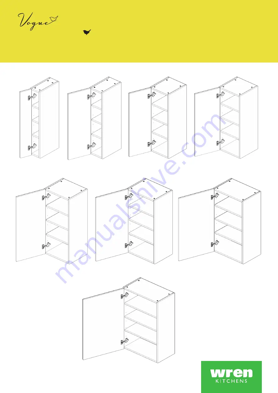
WALL UNIT
150 - 600 Tall 1 Door Assembly Guide
For Internal Use: FI.WR.INS.045.WKIN00130_WALL_150-600_Tall_1Dr.Rev7
150 Tall
400 Tall
300 Tall
450 Tall
600 Tall
350 Tall
500 Tall
200 Tall
Page 1: ...WALL UNIT 150 600 Tall 1 Door Assembly Guide For Internal Use FI WR INS 045 WKIN00130_WALL_150 600_Tall_1Dr Rev7 150 Tall 400 Tall 300 Tall 450 Tall 600 Tall 350 Tall 500 Tall 200 Tall ...
Page 2: ...Screw M x2 Cover Cap N x1 Door Buffer Z x12 Shelf Peg Plastic T x10 Back Panel Support Clip HANGING BRACKET PLATE x2 Screws NOT included HINGE MOUNTING PLATE x2 Inc Screws HINGE x2 Inc Screws CORNER GUSSET x2 HANGING BRACKET COVER CAP x2 Panel B x2 End Panel Panel C x2 Base Panel Frontal packed separately x1 Loose Shelf x3 BEFORE YOU START INSTALLATION SHOULD BE PERFORMED BY A COMPETENT PERSON ONL...
Page 3: ...l cam locks H this will expand the cam dowels G and tighten the unit together NB All cam locks H are to be positioned facing the outside of the unit Carcase for ease of tightening Do not use power tools with cam dowel G or cam lock H Dowel F Cam Dowel G location detail B A C C G G F F F F G G Viewfromunderside Viewfromunderside B C C H H G G Step 1 Seat dowel F into holes in both end panels B as s...
Page 4: ...ange in positions as shown Ensure panel A is seated into the groove of panel B Step 9 Insert cam lock H Hand tighten all cam locks H this will expand the cam dowels G and tighten the unit together NB All cam locks H are to be positioned facing the outside of the unit Carcase for ease of tightening Do not use power tools with cam dowel G or cam lock H B B A C C Dowel F Cam Dowel G location detail S...
Page 5: ...T should be evenly spaced as shown and positioned to allow the hanging bracket and corner gussets to be fitted Once in place tighten screw Step 10 Ensure unit is square A A T T B A C 126mm 126mm 94mm 94mm From Top From Bottom Step 12 Attach hinge mounting plates onto both end panels B in locations shown using screws L which are already positioned within the hinge plates ...
Page 6: ...ides as shown Care to be taken Hanging procedure is necessary for a safe installation Screws for attaching to walls are not provided as these vary depending on materials thickness and construction Ensure appropriate fixings for wall construction are used L L L L Detail B Step 15 Drill a small pilot hole through the centre of the corner gussets through the back of the unit Use this hole at the end ...
Page 7: ...racket Plate Step 18 Using points a b c adjust the unit to suit Step a Rotate the screw clockwise to move the unit up Anti clockwise for down Step b Adjust the depth using centre screw Step c Screw the red screw until it touches the plate to lock in position Hanging Bracket viewed through Back Panel b C c a a b K Step 19 Screw into any side units using the provided 2 x 30mm screws K to secure the ...
Page 8: ...ure Hinge Cover Caps Step 24 Fit cover caps to hinge Adjust Soft close to suit Step 23 Adjust hinge to suit As shown below To adjust hinge using a screw driver tighten or loosen as required at points 1 2 Point 1 In Out Point 2 Left Right 1 2 FRONTAL HINGE ADJUSTMENT Hinge Plates View from inside of unit To release door pull catch as shown to release hinge from the hinge plate The top and bottom hi...