- 8 -
this outline, and a top slice if you’ve decided to have your receiver embedded below the
surface. Mark the top of the slice(s) with an “x” for later reference and discard the remaining
piece of the plug.
41.
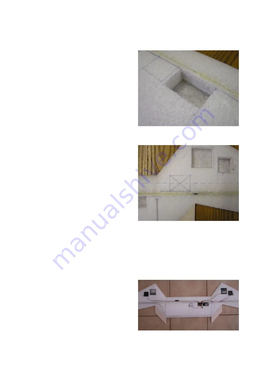
Glue the bottom slice of the foam plug into
the bottom of the receiver cut-out hole
forming a base for the receiver recess. Use
the marks on its front side and top to
orientate it correctly, ensuring a perfect fit.
If you have a top slice, put it aside for later
use as lid over the receiver.
42.
Mark out an area next to the receiver to
accommodate the excess length in the
battery
and
servo
leads.
An
area
approximately 30mm by 40mm (1 3/16” by
1 9/16”) is usually plenty. Cut out a foam
plug using the same method used for the
receiver and servo recesses and glue back in a 5mm to 10mm (3/16 to 3/8”) slice to form a
base. Keep the remainder of the foam plug for later use.
43.
Decide if you wish to install an optional
ballast system such as ballast boxes or
ballast tube(s). Ballast is removable lead
weight positioned exactly on the glider’s
centre of gravity (CG) so that it increases
the model’s weight without affecting the
model’s point of balance. Increasing the
Booby’s weight (higher wing-loading) will
improve it’s penetration in very windy
conditions (over 30 knots) resulting in
increased speed. Given that the Booby
already has quite a high wing-loading
when un-ballasted and is a fast low drag
design, we do not believe that provision for ballast is necessary, so simply mention it here as
an option without going into installation details. If two ballast boxes or two ballast tubes are
installed they can be positioned at the Booby’s CG (140mm back from the noses) in the
middle of each intermediary panel (between central wing panel and outer panel). A single
ballast tube should also be able to fit into the leading edge of the central panel at the CG but
would forfeit compliance with combat competition rules.
44.
Cut slits into the top surface of the wing to accommodate the battery lead and servo leads.
The receiver antenna should be kept a little clear (and avoid any crossing) of the servo leads,
battery leads and spar to avoid possible interference with the radio signal from the
transmitter. Cut a slit for the receiver
antenna that loops around the fin slot and
then runs about 20mm (3/4”) in from the
central panel’s foam sub-trailing edge and
then out to the wingtip.
45.
Fit the battery pack, receiver and servos
into their recesses. Plug everything
together and test that it is working
correctly. The two standard size aileron


