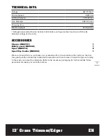
Worx WG190 Operating Instructions Manual Download Page 12

12

13

 Grass Trimmer/Edger

EN

line will not feed properly and will result in 
improper cutting head function or can cause 
serious injury. Do not use other material such 
as wire, string, rope, etc. Wire can break off 
during cutting and become a dangerous 
projectile that can cause serious injury.

Trimming

Postion the trimmer head as shown in Fig. G1 
for trimming. 
Keep the bottom of the trimmer head just 
above the ground and at an angle. Allow only 
the tip of line to make contact. Do not force 
trimmer line into work area.

Edging (See Fig. G1, G2, G3, G4)

AlwAyS REmoVE THE BATTERy 

PACk BEFoRE AdJuSTiNG THE 

TRimmER HEAd PoSiTioN.

For edging, position the trimmer head as Fig.G2.
To rotate the trimmer head to edging—first 
hold the trimmer shaft as shown in Fig G3---
then with your other hand hold the trimmer 
head - Push down and rotate 180 degrees and 
then release- the trimmer will then lock into 
the edging position automatically—Fig G4

NoTE: 

The trimmer head will only rotate in 

one direction. While rotating, please remove 
the battery from your tool for your safety.
The edge guide helps protect the unit and 
keeps the unit from contacting the ground. 
Take extra caution while edging as objects can 
be thrown from the trimmer line.

AuTomATiC liNE FEEd SySTEm

When initially switching ON the trimmer, a 
small length of line is fed out.
A ‘clattering’ noise will be heard when 
the lines hit the line cutter. 

do NoT BE 

AlARmEd

, this is normal. After a few  

seconds the line will be cut to the correct 
length and the noise will reduce as the motor 
receives full speed.
If the noise of the line being cut can’t be heard, 
more line will need to be fed out.
To feed more line, it is first necessary to allow 
the trimmer to stop completely, then restart, 
allowing the motor to reach full speed.
Repeat above until you hear the lines hitting 
against the line cutter.

To mANuAlly FEEd THE liNE 

(See Fig. H1)

AlwAyS REmoVE THE BATTERy 

PACk BEFoRE AdJuSTiNG THE 

TRimmER HEAd PoSiTioN.

If required, line can be feed out manually
To operate, press and release manual line feed 
button (15), while gently pulling out the line 
until it is long enough to reach the line cutter.
If the line extends past the line cutter, too 
much line has been fed out.
If too much line is fed out, remove the spool 
cap and turn spool counter-clockwise until the 
line is at the desired length.

To REmoVE THE CAP (See Fig. H2)

 Press and hold the two latches (11).

 Pull cap away from the spool holder

 When refitting the spool cap, keep all areas 

of the cap and spool holder clean.

 Replace the cap, pressing firmly down 

towards the spool holder to ensure cap is fully 
located into position.

 Check that the cap is correctly fitted by trying 

to remove it without depressing the two 
latches.

REPlACE THE TRimmER liNE ANd 

SPool (See Fig. i).

AlwAyS REmoVE THE BATTERy 

PACk BEFoRE AdJuSTiNG THE 

TRimmER HEAd PoSiTioN.

 Remove Spool Cap Cover.

 For your convenience it is recommended you 

buy replacement spools with the trimmer line 
preinstalled.

 Remove the old Spool from Spool Holder. 

Clear any broken line or cutting debris from 
the spool area.

 Pull the line from the new replacement Spool 

through the eyelet of the Spool Holder. 

 Place new Spool into the holder with the cut 

out areas of the Spool facing inward or down. 
When installed into the Spool Holder, the 
smooth side of the Spool should be visible. 

 Release line from cleat on the Spool.

 Refit the Spool Cap Cover.

Summary of Contents for WG190

Page 1: ...WG190 HElPliNE NumBER 1 866 354 woRx 9679 HElPliNE NumBER 13 Grass Trimmer Edger EN Coupe gazon Taille bordure 13 F 13 Cortadora de cesped Ribeteadora ES P06 P15 P25...

Page 2: ......

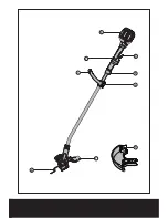
Page 3: ...2 3 1 6 8 7 5 9 4...

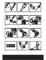
Page 4: ...Click Click Click A1 A2 B1 B2 C1 C2 C3 D1 D2 E F G1...

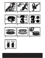
Page 5: ...RIGHT WRONG 15 10 11 12 13 14 G2 G3 G4 H1 H2 I J1 J2 J3 J4...

Page 6: ...b 6 Auxiliary Handle Locking Clamp 7 Safety Guard 8 Edge Guide 9 Line Cutter 10 Trimmer Head Cover See Fig H2 11 Cap Release Latch See Fig H2 12 Spool See Fig H2 13 Trimmer Head See Fig H2 14 Eyelet S...

Page 7: ...of 48 volts Nominal voltage is 43 2 volts Accessories Charger WA3741 1 battery pack WA3538 1 spool WA0014 2 Spool Cap Combo WA0204 1 We recommend that you purchase your accessories from the same stor...

Page 8: ...educe the risk of injury Follow instructions for lubricating and changing accessories Keep handles dry clean and free from oil and grease 12 Check Damaged Parts Before further use of the appliance a g...

Page 9: ...p battery out of reach of children and in original package until ready to use 4 Never put batteries in mouth If swallowed contact your physician or local poison control center 5 CAUTION The battery us...

Page 10: ...RY HANDLE See Fig B1 B2 Slide the auxiliary handle onto the grooves of auxiliary handle support until a click can be heard And make sure the auxiliary handle locking clamp is closed See Fig B1 Note Ma...

Page 11: ...tinuing to operate your trimmer with the battery in this discharged condition may reduce the life and performance of your battery 5 SAFETY ON OFF SWITCH Your trimmer has a Lock OFF switch 2 to prevent...

Page 12: ...e heard more line will need to be fed out To feed more line it is first necessary to allow the trimmer to stop completely then restart allowing the motor to reach full speed Repeat above until you hea...

Page 13: ...ol STORING YOUR GRASS TRIMMER Always remove the battery pack from your trimmer after use Store in a dry place where the trimmer and battery can be protected from damage MAINTENANCE Always remove the b...

Page 14: ...erm Grass too high Battery defective Fully charge battery also see the content in charger manual Cut in stages Replace the battery Machine does not cut Line broken Battery not fully charged Motor is b...

Page 15: ...Garde De S Curit 8 Guide de coupe 9 Coupeur De Cordon De Coupe 10 Couvercle de bobine Voir Fig H2 11 M canisme de d verrouillage du couvercle Voir Fig H2 12 Bobine Voir Fig H2 13 T te de coupe Voir Fi...

Page 16: ...volts La tension nominale est de 43 2 V ACCESSOIRES Chargeur WA3741 1 Bloc Piles WA3538 1 Bobine WA0014 2 Combo d bobine support WA0204 1 Nous vous recommandons d acheter tous vos accessoires du m me...

Page 17: ...z alerte Faites attention ce que vous faites Utilisez le bon sens N utilisez pas l appareil lorsque vous tes fatigu 10 Entreposez l int rieur les appareils qui ne sont pas utilis s fr quemment Lorsqu...

Page 18: ...ONS PR CAUTIONS SUPPL MENTAIRES POUR L UTILISATION DU COUPE BORDURES 1 Gardez les carters en place et en bon tat de fonctionnement 2 N UTILISEZ JAMAIS cet appareil SANS que le dispositif de protection...

Page 19: ...es en court circuit par un mat riau conducteur 10 N exposez pas la pile cellulaire ou la batterie des chocs m caniques 11 Gardez les piles cellulaires et les batteries propres et s ches Essuyez les bo...

Page 20: ...dans les bornes de connections de votre chargeur ou bloc pile parce qu une d faillance lectrique et un danger vont se produire 1 AVANT D UTILISER VOTRE TAILLE BORDURE SANS FIL Votre bloc pile n est PA...

Page 21: ...e en place en toute s curit INSTRUCTIONS D UTILISATION AVERTISSEMENT Toujours porter des lunettes de s curit et des v tements protecteurs afin d viter que des roches et d bris vous frappent ou vous c...

Page 22: ...ent sur le cordon de coupe jusqu ce qu il atteigne le coupeur de cordon de coupe Lorsque la quantit voulue de cordon de coupe est sortie tirez doucement sur le deuxi me cordon de coupe il n est pas n...

Page 23: ...es dommages V rifiez toujours l appareil avant de l utiliser pout toute indication de dommage N utilisez jamais votre appareil s il est endommag Votre outil lectrique ne requiert pas de lubrification...

Page 24: ...r la batterie Appareil ne coupant pas Fil bris Batterie partiellement d charg e Moteur bris r gime moteur trop bas Tiges d herbe entrem l es aurour de la t te coupante Remplacez la ligne Recharger bat...

Page 25: ...ngo 7 Guarda protectora de seguridad 8 gu a de la rebordeadora 9 Cuchilla del hilo 10 Cubierta de la tapa de la bobina Ver Fig H2 11 Pestillo para extracci n de la tapa Ver Fig H2 12 Bobina Ver Fig H2...

Page 26: ...de la bater a alcanza un m ximo de 48 V El voltaje nominal es 43 2 V Accesorios Cargador WA3741 1 Bater a WA3538 1 Bobina WA0014 2 Combinado de Bobina Tapa WA0204 1 Le recomendamos que compre todos lo...

Page 27: ...o est cansado 10 Guarde las herramientas que no usa en lugares cerrados Cuando no se encuentran en uso las herramientas deben guardarse en un lugar seco elevado o cerrado con llave lejos del alcance d...

Page 28: ...l siguiente mensaje o similar Conserve estas instrucciones INSTRUCCIONES DE SEGURIDAD ADICIONALES PARA LA CORTADORA DE C SPED 1 Mantenga las guardas en su ubicaci n y en condiciones de funcionamiento...

Page 29: ...celdas o bater as en forma peligrosa en una caja o caj n donde puedan hacer cortocircuito entre s o con materiales conductivos 10 No someta las celdas o bater as a descargas mec nicas 11 Mantenga las...

Page 30: ...a pues incurrir a en peligro de aver a el ctrica 1 ANTES DE USAR SU DESMALEZADORA INHAL MBRICA Su bater a est DESCARGADA y debe cargarla antes de usarla El cargador de bater a suministrado est dise ad...

Page 31: ...un desmalezado y bordeado ptimos sin perder su comodidad mantenga el cabezal de corte paralelo al suelo cuando efect e desmalezado perpendicular en operaci n de bordeado Durante el desmalezado aseg re...

Page 32: ...a bobina y el interior del cabezal de corte Para volver a colocar la cubierta de la tapa de la bobina presi nela firmemente hacia el soporte de la bobina Aseg rese de que est instalada de forma correc...

Page 33: ...Advertencia Apague la herramienta y extraiga la bater a antes de efectuar la resoluci n de problemas Problemas Posibles causas Acci n correctiva La podadora no funciona Bater a descargada Bater a dem...

Page 34: ...nte la bater a en el cargador de bater as Limpie los contactos de la bater a por ejemplo colocando y extrayendo varias veces la bater a Reemplace la bater a Reemplace la bater a El indicador de carga...

Page 35: ......

Page 36: ...Designed in Italy Made in China Con u en Italie Fabriqu en Chine Dise ado en Italia Fabricado en China Copyright 2013 Positec All Rights Reserved...

Reviews: