background image

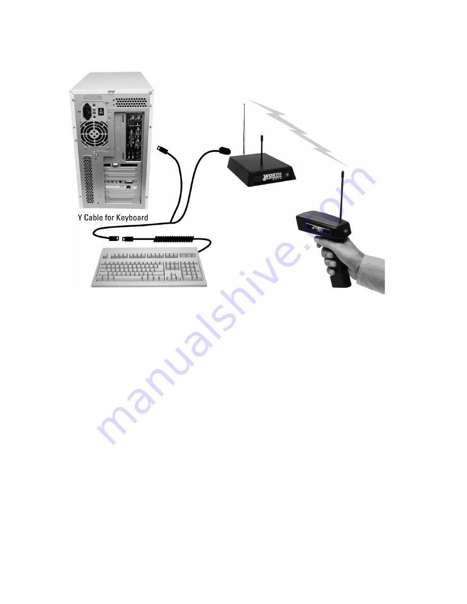
Your computer, keyboard and reader should now be cabled as shown below: 


Turn on your computer:  
 
You will hear three beeps on the 1-way Base Stations, and the LED on the 
front will change from red to green, indicating that the Base Station is 
functioning correctly. The 2-way base will simply flash to green. If you have a 
PS/2 or a Mac, you will have to change the Computer Interface using the 
Wireless Setup Menu. Turn to page 9 to configure your RF Reader using the 
Wireless Setup Menu.  
 

Summary of Contents for LI101-RF

Page 1: ...Worth Data Inc Wireless Reader Manual 01 05 ...

Page 2: ...Connect the equipment into an outlet on a circuit different from that to which the receiver is connected Consult the dealer or an experienced radio TV technician for help Shielded cables and I O cords must be used with this equipment to comply with the relevant FCC regulations Changes or modifications not expressly approved in writing by Worth Data Inc may void the user s authority to operate this...

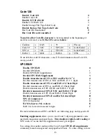
Page 3: ...hooting 33 Opening the Base Case 37 Jumper Settings 38 Specifications for Code 39 39 Code 39 Advanced Features and Functions 40 Code 93 Specifications 42 Codabar Specifications 43 Codabar start stop transmission 43 Code 128 Specifications 44 Interleaved 2 of 5 Code 46 UPC Specifications 48 ISBN Specifications 49 The UPC EAN checksum character 50 Checksum calculation for UPC A EAN 13 and EAN 8 50 U...

Page 4: ......

Page 5: ...s with the B54 B64 Base Station at 40 66MHz in continental Europe The LZ200 RF Laser L60L in Europe and the LI101 RF Linear Imager CCD LI111 RF in Europe transmit to a base station that attaches to the keyboard port of a PC or Mac or any computer s serial port These 1 way products require the user to listen for a beep at the Base Station to know that the Base has received the transmitted data The ...

Page 6: ... and C20 cable instead of a Y cable 5 A wireless scanner Laser or Linear Imager CCD Included is a rubber boot housing to place over the Laser or Linear Imager for durability 6 A Laser Linear Imager CCD holder 7 A laminated Wireless Reader Setup Menu sheet 8 If a serial interface model was ordered a Worth Data 5v regulated power supply DON T USE ANY OTHER POWER SUPPLIES OR YOU WILL BURN UP THE BASE...

Page 7: ...eature DO NOT PLUG ANY OTHER POWER SUPPLY into the Base Station or it will be fried burned up 1 Power down the computer Turn OFF the power on the computer Failure to power down risks blowing shorting a trace on the computer 2 Unplug the keyboard cable from where it plugs into the computer 3 Plug the keyboard cable into the Y cables round female DIN connector The F30 1 Y cable is convertible from 5...

Page 8: ...tations and the LED on the front will change from red to green indicating that the Base Station is functioning correctly The 2 way base will simply flash to green If you have a PS 2 or a Mac you will have to change the Computer Interface using the Wireless Setup Menu Turn to page 9 to configure your RF Reader using the Wireless Setup Menu ...

Page 9: ...ou plug the Wedge Saver to the USB port on a Mac or PC Windows 98 ME XP and 2000 the device will be sensed will sensed and installed Windows finds the necessary driver usually on the hard drive you don t need any additional drivers other than what is already on Windows or Mac OS After the software installation completes follow these instructions 1 Plug the Wedge Saver into a USB port on the host c...

Page 10: ... or a 9 pin cable part number F36 when you placed your order you can cable directly from the RF Reader s Y Cable port to your computer s serial port Refer to page 8 for the details of the pin outs of the cables Serial extension cables longer than 80 feet can cause system lockups in Windows unless you make sure that pins 4 6 7 and 8 are cut on the 9 pin end of the F36 cable and pins 4 5 6 8 and 20 ...

Page 11: ... for each connector on the cable You will also need to change jumpers JP2 on the RF Base on the board inside the case from the S position to the Y position Cables may require modification depending on the genders and pin outs of your serial ports and cables You may require gender changers available at most computer stores for the two 25 pin connectors Refer to page 8 for the details of the pin out...

Page 12: ...4 5 On the DB9 pin end pins 4 6 7 and 8 are NOT connected in cables sold after 9 15 01 If you are using an older F36 cable and a serial extension cable longer than 80 ft cut pins 4 6 7 and 8 at the DB9F end of the F36 cable to avoid system lockups in Windows F45 1 Dual Port Serial Cable If you want to install the Base between a serial terminal and a host computer as with Unix PICK VM etc you need ...

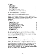
Page 13: ...1st 2 characters Start stop characters not transmitted and check digits transmitted 2 of 5 Code UPC E NSC and EAN 8 1st 2 characters Disabled check digits not transmitted I 2 of 5 Code Disabled General configuration settings 6 digit code length PC or RS 232 Computer Interface Check digit disabled Autosense Code 128 CR for Terminator Character Disabled Data Transmission Timing of None UCC EAN 128 o...

Page 14: ...irst example below For both the laser scanners and the Linear Imager CCD s you ll need to hold the scanner further away to produce a wider beam for large bar codes and closer for bar codes with bars very close together Even though momentary exposure to a laser s low power visible light is not known to be harmful you should not aim the beam into anyone s eyes The important thing to remember about u...

Page 15: ... Now scan the 4 on the Barpad Table You will again hear two beeps On the 2 Way RF products Laser and Linear Imager CCD the beeps will be in the scanner on the 1 Way RF products Laser and Linear Imager CCD the beep will be at the Base Station ONLY 4 Now scan End Setup at the top right corner of the Reader Setup Menu to complete the setup exercise You ll hear three beeps on the Base Stations or 2 Wa...

Page 16: ...nformation about Code 39 and Full ASCII Code 39 see Appendix C See page 28 for information about Accumulate Mode Enabling Start Stop character transmission means that the Radio Freedom Reader will transmit the Start Stop characters to your computer along with the data For example data of 1234 would be transmitted as 1234 Enabling the Mod 43 Check Digit requires the units position of your data to m...

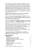
Page 17: ...t 2 4 Disable transmission of UPC A NSC and EAN 13 1 st 1 digits 5 Enable transmission of UPC A and EAN 13 Check Digit 6 Disable transmission of UPC A and EAN 13 Check Digit 7 Enable transmission of UPC E NSC and EAN 8 1 st Digit 8 Disable transmission of UPC E NSC and EAN 8 1 st Digit 9 Enable transmission of UPC E and EAN 8 Check Digit A Disable transmission of UPC E and EAN 8 check Digit B UPC ...

Page 18: ...13 If you wish to transmit UPC A data in EAN 13 format an added leading 0 for the USA s country code scan Terminator Character and F Scanning E the default sets UPC back to no country code transmitted ISBN International Standard Book Numbering bar codes are EAN 13 codes with a 5 digit supplement If the first three digits are the Bookland country codes of 978 for books or 977 for periodicals then y...

Page 19: ... 7 For information about Interleaved and Standard 2 of 5 see Appendix G Enabling the Check Digit requires the data s units position to match the calculation for the check digit explained in Appendix F If you ve enabled the check digit enabling Check Digit transmission causes the reader to transmit it to your computer along with the bar code data 2 of 5 Data Length 2 of 5 Code is so susceptible to ...

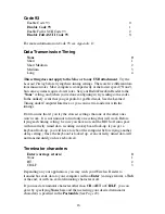
Page 20: ...Don t assume that if you try the slowest settings that one of the other ones won t work It is not unusual to find only one setting that will work Before trying each timing setting be sure you have not sent the BIOS off into space with incorrectly timed data resulting in a keyboard lock up if you get a keyboard lock up you will have to reboot the computer before trying another delay setting Once th...

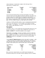
Page 21: ...I Data Format 3 RS 232 PC Terminal Mode Data Format 4 RS 422 ASCII Data Format 5 RS 232 ASCII is used for almost all serial ports and terminals PC Terminal Mode refers to the very rare Concurrent DOS RS 422 applies to the RF Bases and is used with RS 422 boards only Preamble A Preamble is a user specified data string transmitted at the beginning of each bar code For example if you specify the prea...

Page 22: ...two digit maximum to be read Postamble Postamble refers to a user specified data string transmitted at the end of each bar code For instance if you specify the postamble and read data of 123456 123456 would be transmitted to your computer The default is no postamble To select a postamble scan up to 15 characters from the FULL ASCII MENU on the back of the Reader Setup Menu and then scan SET when y...

Page 23: ... for each character You can also eliminate characters by reassigning hex codes to FF For example to strip all dollar sign characters from transmission you would follow the above instructions and scan 2 4 F F in step 3 Keyboard country This option configures the Radio Freedom Reader for your choice of 15 keyboard country settings such as USA the default UK French German etc Scan the keyboard countr...

Page 24: ...ireless Scanner and its Base Station without transmitting data You can use this to be sure you are in range and able to hear the base station beeping No data is transmitted Do not enter the Setup Mode when performing the link test This code is the same as the Clear Buffer code on the Barpad Menu Reset Once you are in the Setup Mode don t scan Reset unless you re sure you want to restore the Wirele...

Page 25: ...eturn to the computer be certain that the screen and cursor are properly positioned and then pull the trigger again for transmission The first trigger pull scans and stores the bar code The second trigger pull transmits the data permitting the user to be sure the cursor is properly positioned To change the reader to Delayed Transmission Scan Start Setup Scan Terminator Scan B to select delayed tra...

Page 26: ...you can do to facilitate reading the VIN 1 Be sure the window on the laser scanner is clean 2 Be sure the windshield is wiped before of reading The following parameters apply serial models of the base stations only If you are using keyboard wedge models of the base stations please skip to page 25 Baud rate 300 0 600 1 1200 2 2400 3 4800 4 9600 5 19 200 6 Data bits 7 Bits 0 8 Bits 1 Set the data bi...

Page 27: ...m which it has just received transmitted data without waiting for a response from the host computer program If you want the host computer program to analyze the data and to send back different beep patterns to the laser scanner enable Host Controlled Acknowledge With this parameter enabled when the serial models of the 2 way base station receives data from an R F Scanner the data is passed to the ...

Page 28: ... response is so fast it is not necessary to change this parameter However if you have a very complicated program that must access multiple databases for each data item transmitted you may need to specify additional delay Test the Reader with your computer If you are connected by keyboard interface or if you have a serial reader and are using PortKey with an IBM compatible you should be able to sca...

Page 29: ...Windows only If you are using the WDR Serial Test Program follow these guidelines Make sure the serial parameters on your Base Station match those used by your computer Make sure you are connected to a valid serial port If you still are having problems see the Troubleshooting Section ...

Page 30: ...beeper in them there is a beeper in the 2 way RF Laser but not in its base Therefore if you are out of hearing range of the one way base station s beeper you cannot know if scanned data was successfully transmitted to the computer or if the scanned data was not successfully decoded and therefore not transmitted The big mistake you must avoid is UNKNOWN DUPLICATE DATA ENTRY unknowingly reading mult...

Page 31: ... lost even though you have wandered out of range of the Base Station Until the pending data acknowledgment has been received pulling the trigger will only retransmit and not activate the scanning laser beam for additional reading If you are out of range and want to clear data in the scanner s buffer waiting to be transmitted again by pulling the trigger and holding it down for 15 seconds the buffe...

Page 32: ...the setup of another base and or associated laser scanners Otherwise all base stations that can hear will be set to the same ID Character and its purpose will be defeated Base Station IDs are a z and Scanner IDs are 1 8 This is not recommended because of interference However occasionally there will be need for more base stations than the number of available frequencies Providing that you keep the ...

Page 33: ...ead and buffer bar codes up to 40 characters until it reads a bar code without a leading space Then the entire buffer including that last code is transmitted as one long bar code A bar code of a double minus sign clears the buffer Scanning a backspace code H backspaces in Full ASCII mode A handy code for Enter as seen on the Barpad below is a Start Stop only No data The code to use for testing the...

Page 34: ...SCII Menu Bar Code F1 F1 SOH f1 F2 F2 STX f2 F3 F3 ETX f3 F4 F4 EOT f4 F5 F5 ENQ f5 F6 F6 ACK f6 F7 F7 BEL f7 F8 F8 SO f8 Numpad 5 Enter LF Enter Return CR F9 F9 SI f9 F10 Cmnd On DLE f10 Del Del DC1 Del Insert Cmnd Off DC2 Ins Left Arrow Left Arrow DC3 Rt Arrow Rt Arrow DC4 Dn Arrow Dn Arrow NAK Up Arrow Up Arrow SYN Pg Up Pg Up VT Pg Up Pg Dn Pg Down FF Pg Dn Home Home ETB Home End End CAN End S...

Page 35: ... If you scan bar codes mapped to the control keys on the far right of the keyboard you will get numbers because the Mac USB keyboard is always in Num Lock On other keyboards if you want your application to be immune to the setting of the Num Lock key use the bar codes mapped to the Center Control Keys instead of the keys on the Full ASCII menu The below chart corresponds to the small center sectio...

Page 36: ...ows key ON OFF bar codes NULL C Command ON and NULL D Command OFF For the Option Key ON OFF use RS Option On and US Option Off If you have an older Worth Data Reader before 6 99 you can also imitate the Command Key by key codes in the Preamble Postamble To transmit Command N would be E01F N E0F01F Transmitting any ASCII character using its 3 digit ASCII code You can also transmit any ASCII charact...

Page 37: ...age 28 will not be transmitted to your computer until you read a bar code without a leading space Try reading the Test Label on page 25 as an example of a known good label without a leading space If you have bar codes with leading spaces in them and you want them transmitted you must disable Accumulate Mode using the Setup Menu Reread the configuration section and make sure you properly enabled th...

Page 38: ... supply it must be regulated and must be the right polarity otherwise you will damage the Base Station Order a 5 volt external power supply feature code F10 or 110V F11 for Euro 220 and F14 for the UK The reader transmits incorrect data to the screen Reread page 17 and make sure you chose the proper Computer Interface If part of the data is correct and part missing first try the PC Keyboard Learne...

Page 39: ...t in your software Run the WDR Serial Test Program that shipped with your reader and see if it gets any data on the screen when you read a bar code Use a null modem connector to test switching pins 2 and 3 on one or more serial cables or use a breakout box to modify your cable s The reader doesn t beep when you try to read your bar codes Make sure the power adapter is plugged in Try reading a know...

Page 40: ... F34 cable All F36 9 pin serial cables shipped after 9 15 01 have pins 4 6 7 and 8 cut at the DB 9 end of the cable If you have one of the older cables or have built your own you need to cut pins 4 6 7 and 8 at the 9 pin end of the cable see page 8 for details on which pins should remain connected All F34 25 pin serial cables shipped after 9 15 01 have pins 4 5 6 8 and 20 cut at the DB25 end of th...

Page 41: ...blade into the gap between the base and side of the case Gently use it as a lever to lift up the edge of the base then grasp the edge of the base and open it outward like a door This exposes the reader s circuit board as shown below Next you will need to remove the shiny metal shield to expose the jumpers Use the same flat head screwdriver to lift up the top of the metal can Now you can see the ju...

Page 42: ...k from Serial to Keyboard Kybd You will need a serial cable too the keyboard Y cable won t work with serial Serial Users if you are going to use the Serial Y Cable F45 1 you will need to change the JP2 Jumper 2 from S to Y This permits Half Duplex transmissions and interface between a host and terminal If you need RTS CTS hardware handshaking call us for more information The below diagram shows th...

Page 43: ...Each character is formed of three wide and six narrow elements made up of five bars and four spaces Code 39 s density can vary from a low of 75 characters per inch cpi to a high of 9 4 cpi There should be a quiet zone white space to the left and right of the bar code Code 39 uses an asterisk as a start and stop character This character must precede and follow the data in the bar code The Wireless ...

Page 44: ...5 3 3 E 14 P 25 36 4 4 F 15 Q 26 37 5 5 G 16 R 27 space 38 6 6 H 17 S 28 39 7 7 I 18 T 29 40 8 8 J 19 U 30 41 9 9 K 20 V 31 42 A 10 L 21 W 32 Table C 1 Mod 43 Check character calculation for Code 39 Here is an example to illustrate how the check character is calculated for bar code data of 123XYZ 1 Take the sum of the values assigned to each character 1 2 3 33 34 35 108 1 2 3 X Y Z 2 Divide the su...

Page 45: ... of Code 39 characters ASCII Code 39 ASCII Code 39 ASCII Code 39 ASCII Code 39 NUL U SP Space V W SOH A A A A a A STX B B B B b B ETX C C C C c C EOT D D D D d D ENQ E E E E e E ACK F F F F f F BEL G G G G g G BS H H H H h H HT I I I I i I LF J J J J j J VT K K K K k K FF L L L L l L CR M M M m M SO N N N n N SI O O O O o O DLE P 0 0 P P p P DC1 Q 1 1 Q Q q Q DC2 R 2 2 R R r R DC3 S 3 3 S S s S DC...

Page 46: ... pairings for Code 39 Code 39 uses M to produce a Carriage Return ASCII 13 character Code 93 uses M to produce the Carriage Return Code 93 s two built in check digits greatly minimize the possibility of reader substitution errors These check digits are never transmitted by the bar code reader Code 93 s Start and Stop characters are also never transmitted If you have not decided which bar code type...

Page 47: ...tify different types of labels Codabar s variable data length and extremely low error rate make for a versatile bar code Codabar start stop transmission The Codabar section on the Wireless Reader Setup Menu lets you determine whether Codabar start stop characters are transmitted or not If you are varying start stop characters with different types of labels you ll want to Enable Stop Start characte...

Page 48: ...ses an internal Mod 103 check character that is not displayed by the bar code reader Code 128 bar codes can be made up of only one subset or may be a combination of several The Code 39 features of Accumulate Mode Caps Lock ON and Caps lock OFF also apply to Code 128 UCC 128 EAN 128 UCC 128 EAN 128 Code is a subset of Code 128 adopted by the UCC and EAN council s for use as a shipping label symbolo...

Page 49: ...es as well as the UCC EAN 128 bar codes with the Function 1 character and the Mod 10 check character The UCC 128 specification is used extensively by the retail industry If you have a requirement for a UCC 128 Serial Shipping Container bar code be sure to follow the specification as closely as possible as many vendors will impose fines for non conformance For more information on UCC EAN 128 contac...

Page 50: ... of 5 code only By default the Wireless Reader is set to look for a 6 digit I 2 of 5 code but you can set the length to something different using the Wireless Reader Setup Menu Setting the length to 00 digits allows variable length bar codes scanning but also dramatically increases your chance of a mis read Use a check digit Worth Data s LabelRIGHT printing program automatically calculates and pri...

Page 51: ...ct the result of step 5 from the next highest multiple of 10 60 57 3 7 The checksum becomes the low order digit 19873 8 Because the data now has an odd length a leading zero is added for the final result of 019873 ...

Page 52: ... code containing seven data digits and ending again with a checksum The exact UPC EAN symbol specifications are available from Uniform Code Council Inc 7887 Washington Village Drive Suite 300 Dayton OH 45459 937 435 3870 937 435 7317 info uc council org 8 00 a m to 6 p m EST Specifications are also available via the Internet at http www uc council org Keep the following guidelines in mind when pri...

Page 53: ... of a 2 or 5 character supplemental code used with magazines and paperback books To read the supplements you must first enable them using the Wireless Reader Setup Menu NOTE Enabling the supplements disallows the reading of UPC codes from right to left to assure that the supplement does not get missed ISBN Specifications ISBN International Standard Book Numbering bar codes are essentially EAN 13 w...

Page 54: ...gn even and odd positions starting at the right and moving left 8 3 9 9 8 5 4 1 3 8 1 odd even odd even odd even odd even odd even odd 1 Starting with the leading digit 8 take the sum of all the characters in the odd positions 8 9 8 4 3 1 33 2 Multiply the result of step 1 by 3 33 x 3 99 3 Now take the sum of all the even position characters 3 9 5 1 8 26 4 Add the result in Step 2 to the result in...

Page 55: ...000e 5 abcde5 0000 6 Abcde00005 6 abcde6 0000 6 Abcde00006 7 abcde7 0000 6 Abcde00007 8 abcde8 0000 6 Abcde00008 9 abcde9 0000 6 Abcde00009 Because the sample UPC E code ends in a 6 the insertion digits 0000 are inserted at the sixth digit insertion position 6 1234500006 2 Add the Number System Character of 0 to the sample data 01234500006 3 Use the UPC A check digit calculation described in the p...

Page 56: ...wise it has a maximum length of 13 characters This is how the MSI check digit s are calculated The MSI Mod 10 check digit is calculated as follows The example bar code data is 82345 1 Form a number from the odd positions starting in the units position 835 2 Multiply the new number by 2 835 x 2 1670 3 Add the digits of product 1 6 7 0 14 4 Add the even digits of the original number to the result in...

Page 57: ... example the 2 up to the highest order position the 9 Use checking factors of 2 3 4 5 6 7 2 3 4 5 6 7 2 Multiply the checking factor with its assigned number and add the products 4 12 32 35 30 28 6 12 36 195 3 Divide the sum by 11 195 11 17 remainder 8 4 Subtract remainder from 11 11 8 3 5 New Check Digit 3 If the remainder is 10 no check digit is added 6 Data with check digit is 943457823 ...

Page 58: ... the nipples aimed at the scanner head The two batteries which go into the outside tube must have the nipples oriented pointing towards the bottom of the handle Since we have tested the Scanners at about 50 000 to 70 000 scans per set of alkaline batteries changing should be relatively infrequent After changing the batteries slide the battery cover back in place Notice that the underside of the ba...

Page 59: ... it must match the groove in the socket that it is to be inserted into Don t insert the chip backwards line up the groove in the chip to be on the same side as the socket s groove You may need to slightly bend into the center the legs of the EPROM so that they can be inserted into the socket Place the chip into the socket and begin to lightly push the chip into the socket Unless you check you may ...

Page 60: ...56 ...

Page 61: ...C Cables may require modification 8 testing with Half Duplex 23 types 3 5 8 Caps Lock 12 34 35 CCD Scanners how to use 10 Center Control Keys 31 Character codes reassigning 19 Characters setup menu parameter 19 Check Character 40 Check digits checksums 40 44 45 46 50 52 and Accumulate mode 29 Code 39 12 Ingterleaved 2 of 5 15 MSI Code 14 UPC EAN 13 Codabar 43 CLSI Format 15 default settings 15 Sta...

Page 62: ...t 5 Interleaved 2 of 5 check digit calculation 46 check digits 15 default settings 15 Interleaved 2 of 5 Code 46 ISBN Specifications 49 K Key sequences emulated 32 Keyboard error 34 Keyboard wedge installation problems 34 Keyboards different countries 19 L Leading characters trimming 17 Leading spaces Accumulate Mode 29 35 Learned timing Keyboard 17 Linear Imager CCDs how to use 10 LOGMARS 39 LZ2x...

Page 63: ...8 36 Serial pinouts 8 Serial transmission test program 25 Serial Y Cable pinouts 8 term port 35 Setup Menu Baud Rate 22 beep tone 12 Code 128 13 Code 39 12 Computer Interface 17 Data bits 22 data transmission timing 16 Keyboard country 19 options 12 Parity 22 Postamble 18 Preamble 17 Protocol 23 Reset 20 Set ID character 19 Stop bits 23 Terminator Character 16 Transmission mode 23 UPC EAN 13 Shift...

Page 64: ...ntry code 13 UPC A in 13 digit EAN format 13 UPC E Checksum Calculation 51 UPC E1 caution if reading EAN 13 14 USB Mac Command Key 31 V Vehicle ID reading 21 22 VIN reading 21 W Wedge installation problems with 34 Windows key mapping 32 Windows system lockups 36 Windshield Reading 21 Wireless Reader components 2 Wireless Scanners default settings 9 Wrong data 21 22 ...

Reviews: