Workhorse Products Javelin PRO Owner'S Manual Download Page 8

 8 

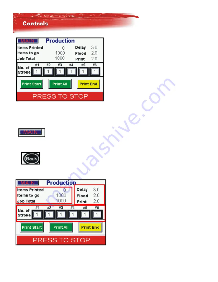
In the Producon screen there are several selecons.  This is the normal screen that you will be running the ma-

chine from in producon.  Changes can me made in here for # of head strokes , me allowed for delay, print or 

flood. and even seeing items printed. 


At the top leK corner of the screens you will see a Main switch.  By 

touching the screen here it will take you directly to the Main Menu 

where all the short cut keys are. 

At the top leK of some screens you will see a Back buIon.  By touching this 

buIon it will take you  back to the previous screen 

In this view of the touch screen there are 3 boxes that are out-

lined in red, each one of these is a Hot key by touching that 

part of the screen it will link you straight to that selecon.  If 

you touch the mer Box, it will take you directly to the mer 

screen, the same as the number of stroke seMngs and the 

items to be printed.  You can make changes with the machine 

running.   

Summary of Contents for Javelin PRO

Page 1: ...PN 67 1540 REV A 4 12...

Page 2: ...machines in the industry that can print and ash on all print heads without sacri cing a color Javelin s print heads and drive systems are smooth and dependable enabling you to take on even the most d...

Page 3: ...60Hz 10 JAV 6 10 13 5 4m 10hp 22cfm 7 6bar 623 l m 110V 50 60Hz 10 JAV 8 10 13 5 4m 10hp 30cfm 7 6bar 850 l m 110V 50 60Hz 10 JAV 8 12 14 5 4 4m 10hp 30cfm 7 6bar 850 l m 110V 50 60Hz 10 JAV 10 12 14...

Page 4: ...3 feet of this equipment when in opera on Do not allow children near this equipment at any me Do not allow this equipment to operate while unaIended Disconnect the power source when crawling under the...

Page 5: ...e underside of the screen to protect from the sharp pallet edge It is necessary that you pre register your screens when burning them for the automa c The highest printed part of your total image shoul...

Page 6: ...od rotate and print Manual Stop In manual mode the table may be raised and lowered using the table up down buIon in the job setup window The table can be rotated manually by hand To print a desired he...

Page 7: ...o tell you the program version of the HMI and PLC The Main Menu is the shortcut screen to each op on in the machine by touching the display it will bring up that screen If you touch the Produc on Key...

Page 8: ...u directly to the Main Menu where all the short cut keys are At the top leK of some screens you will see a Back buIon By touching this buIon it will take you back to the previous screen In this view o...

Page 9: ...arment to a ash longer also Print Start Making this selec on is for puMng your rst garment on the machine or beginning produc on When hiMng print all the rst garment will go to print head 1 and the fo...

Page 10: ...t will pull up a short cut to enter the informa on Print Time is adjusted by selec ng the key or the key or you can touch the screen on the number and it will pull up a short cut to enter the informa...

Page 11: ...used to raise the table and lower them while seMng up a job normally used to check registra on or check o contact Rapid Stroke This will allow the machine to make mul ple strokes ooding and prin ng wi...

Page 12: ...ave all been programmed you can run one shirt with selected heads and num ber of impressions To begin you just select GO and step on the foot pedal or turn the foot pedal o and machine will run automa...

Page 13: ...ensors What in loca on switches have been closed or are open Switches What switches are open and closed Outputs Test all valves on the machine manually to see that it is working correct PLC What input...

Page 14: ...switches If the print head switches are turned o heads 1 6 will register o or on Manual Print buIons if pushed in will register on Manual Mode switch Print valve and Foot pedal can each be checked by...

Page 15: ...head manually move back and forth The liK valve can be tested also by tapping the screen Index valve fork valve and ip valve can also be tested in the same process This feature would be used to test a...

Page 16: ...is the total number of impressions on your machine this is the odometer and can not be reset Contact Informa on This is all the company contact informa on Please feel free to contact us with any ques...

Page 17: ...upwards on the shirt Turning the knobs to the right will cause the image to move down on the shirt MICRO LOCKING HANDLES These handles must be loosened to micro the screens Loosen these Handles only e...

Page 18: ...MICRO REGISTRATION REQUIREMENTS AND TIPS All Micros should be centered on grids before set up Rear clamps should be released when adjus ng front micros more then 1 2 MICRO Adjustment Procedure 1 Raise...

Page 19: ...19 Insert the squeegee tab into ipper block slot Align the squeegee with ipper block hole and insert retaining pin...

Page 20: ...int blade has about 1 2 inch clearance between the edge of the blade and the surface of the screen Push down on the print un l it touches the Pallet The ood blade should now have the 1 2 inch clearanc...

Page 21: ...Use a 9 16th wrench to raise the pallet Use the 9 16th nut on boIom side of the pallet aluminum base to raise the pallet If you need to loosen the uppermost nuts on the Pallet Leveling Bolt even more...

Page 22: ...e s er the shock gets When the table indexes the shock should be adjusted to bring the table to a stop boIoming out all the way without shaking If the shock is to s it will not compress enough on impa...

Page 23: ...resent up to a 6 color press for further instruc ons contact Workhorse Products WARNING RISK OF ELECTRICAL SHOCK Turn ALL power to unit OFF before service All service should be done by or under the su...

Page 24: ...24 390628 2 Note Diagrams only represent up to a 6 color press for further instruc ons contact Workhorse Products...

Page 25: ...25 Note Diagrams only represent up to a 6 color press for further instruc ons contact Workhorse Products...

Page 26: ...26 Note Diagrams only represent up to a 6 color press for further instruc ons contact Workhorse Products...

Page 27: ...lve 2 C5 White 0V Loop S S Red 24V Loop Y5 Org Blk Printhead 6 Stroke Valve X0 Blue Red Org Printhead 1 Manual Switch C6 X1 Wht Blk Grn Printhead 2 Manual Switch Y6 X2 Blk Blue Wht Printhead 3 Manual...

Page 28: ...28 Note Diagrams only represent up to a 6 color press for further instruc ons contact Workhorse Products Head Valves Wiring Plumbing...

Page 29: ...29 Note Diagrams only represent up to a 6 color press for further instruc ons contact Workhorse Products Screen Clamp Plumbing...

Page 30: ...30 Note Diagrams only represent up to a 6 color press for further instruc ons contact Workhorse Products Flip Cylinder and Valve Plumbing...

Page 31: ...te lithium grease on your nger and apply to the rails where the bearings roll Monthly Open up the micros and dab grease on the micro thread bolts and work them all back to center posi ons Clean print...

Page 32: ...oral is expressed or implied Workhorse Products speci cally disclaims the implied warran es of merchantability and tness for a par cular purpose Equipment manufactured or sold by Workhorse Products i...

Reviews: