Work Microwave VHCU User Manual Download Page 20

Satellite Upconverter Manual 


WORK Microwave 


20 / 49


V151207


3.4 Display and Keypad 

All converter functions can be accessed via the front panel display and keypad or via the M&C remote control 
interfaces. 


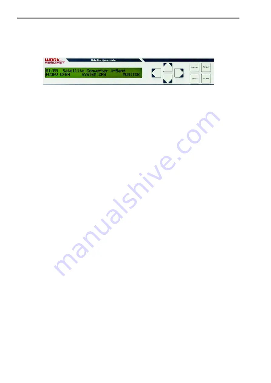
Figure 12: User Interface with display and keypad 

The display has 40 columns, 2 rows. Within standard type units a LCD-Display with illumination, within high 
performance type units a VFD display is used. In case of a VFD display and front panel inactivity a moving 
cursor  is  activated  in  regular  time  intervals  to  achieve  some  protection  of  the  display  against  burn  in.  The 
keypad consists of 4 cursor keys and 4 function keys. The left, right, up or down arrow keys allows to navi-
gate through the menu tree or allow to change the parameters of menu items which were selected for editing. 

If more than one menu items are shown in a main or upper menu, the selected item is indicated with an arrow 
symbol left and right of the menu item. This selection can be done with the left and right arrow keys. 

The  “Enter”  key  opens  the  selected  submenu,  activates  the  selected  menu  point  fo

r  editing  or  confirms  a 

parameter input or change of a parameter. After changing parameters in the edit mode the parameters are 

activated  only  after  confirming  the  selected  values  by  pressing  the  “Enter”  key.  At  the  same  time  the  edit 
mode is  left. The  “Cancel”  key  leaves  selected  submenus  and  leaves  an  edit/change mode  without making 
changes. Pressing the “Ca

n

cel” key in the edit mode discards changes made to parameters in the edit mode 

and leav

es the edit mode. Pressing the “

Cancel

 key again while in the main menu rearranges the main menu 

to it's initial alignment. If a menu item within a submenu allows the change of a parameter this menu item is 

displayed with all capital letters. Pressing the “Enter” key activates the parameter for editing. This is ind

icated 

with an arrow signal left and right of the parameter value. A cursor shows the position within an alphanumeri-
cal  parameter  which  can  be  changed.  The  left  and  right  arrow  keys  allow  to  move  the  cursor.  The  up  and 
down arrow keys allow to change the selected parameter or selected character within the allowed range. 

With the “TX On” key and the “TX Off” key the transmit path can be enabled or disabled.

 It is possible to disa-

ble  these  keys  to  prevent  unintentionally  operation.  This  can  be  configured  with  the  menu  item  "ON/OFF 

KEYS” within the "SYSTEM CFG" menu, which can be set to "Enabled" (keys are operational) or "Dis

abled" 

(keys are not operational). 

3.5 Menu Structure 

The menu is structured in a main menu and submenus. In the following the items of the main menu and the 
submenus are described. Menu items with all capital letters allow changes of configurations. Menu items with 
mainly small letters only allow monitoring of parameters. 

3.5.1 LOCAL or REMOTE 

The  item  “LOCAL"  or  “REMOTE"  is  only  shown  if  the  REMOTE/

LOCAL  feature  is  enabled,  which  can  be 

achieved through a menu point (see 3.5.3.11) with the SYSTEM CFG Menu. This feature allows compatibility 
with other equipment, where configuration access is either exclusively possible locally or remotely. It may be 
also useful to protect from unintended remote configuration (through the M&C interfaces) if the unit is in local 
mode, or from unintended configuration from the front panel, if the unit is in remote mode. If the unit is in local 
mode, and if multipoint configuration commands are received through the M&C interfaces, the error response 
"local mode" is sent back, and the commands are ignored. Status request commands are still possible. If the 
unit  is  in  remote  mode,  the  configuration  menus  "CONV  CFG"  and  "SYSTEM  CFG"  are  not  shown  in  the 
main menu, access to configuration menu points is not possible, also the "TX On" and "TX Off" keys are ig-
nored. 

Summary of Contents for VHCU

Page 1: ...Satellite Upconverter Type VSCU VHCU User Manual WORK Microwave GmbH Raiffeisenstrasse 12 83607 Holzkirchen Germany Tel 49 8024 6408 0 Fax 49 8024 6408 40 E Mail sales work microwave com...

Page 2: ......

Page 3: ...2 Signal Flow 11 2 3 3 Local Oscillators 12 2 3 4 Warm Up Period 12 2 4 Power Supply 12 2 5 Front Panel 13 2 6 Rear Panel 13 2 7 Connectors on the Rear Panel 15 2 7 1 Mains AC Input Connector Block 1...

Page 4: ...3 4 M C INTERFACE SETTINGS 23 3 5 3 5 EXTERNAL MUTE INPUT 24 3 5 3 6 ALARM RELAY 24 3 5 3 7 ALARM RELAY TEST 25 3 5 3 8 FREQUENCY MIN 25 3 5 3 9 FREQUENCY MAX 25 3 5 3 10 FREQUENCY OFFSET 25 3 5 3 11...

Page 5: ...and Parameter Tables 36 4 4 Web Browser Interface 38 4 4 1 Status Indicators 39 4 4 2 Navigation Bar 40 4 4 3 Main Area 40 4 5 Configuration Backup and Restore 40 4 5 1 Local Backup and Restore 41 4 5...

Page 6: ......

Page 7: ...The firmware versions can also be queried by the front panel menu SYSTEM CFG FIRMWARE VERSIONS or by the remote access 1 4 Abbreviations AC Alternating current BNC Bayonet Neill Concelman DC Direct C...

Page 8: ...ned in EN 60950 1 6 Safety Instructions Please read this chapter carefully before you install and use this device from WORK Microwave To ensure your safety please make sure you observe the following i...

Page 9: ...arm environment Pene tration by water increases the risk of electric shock 13 Prior to cleaning the product disconnect it completely from the power supply Use a soft nonlinting cloth to clean the prod...

Page 10: ...3 1 Main Modules The Upconverter has a modular structure The unit consists of four main parts the Upconverter module the main power supply the master communication module Main controller and the user...

Page 11: ...At this IF frequency a linear phase filter selects the correct mixer output signal This filter has a very low group delay distortion In the 2 nd mixer the IF signal at typically 2 45 GHz or 2 44 GHz...

Page 12: ...7 90 8 40 140 2 58 2 44 10 34 10 84 7 90 8 40 X3 70 5 24 5 17 12 17 14 17 7 00 9 00 Ku 70 2 52 2 45 15 20 16 95 12 75 14 50 140 2 58 2 44 15 19 16 94 12 75 14 50 K 70 2 38 2 45 14 85 15 95 17 30 18 40...

Page 13: ...tch 2 6 Rear Panel 1 5 9 7 12 10 2 3 4 14 11 6 8 13 Figure 6 Rear panel 1 Power Supply AC Input 100 240V including mains fuses 2 Alarm mute interface 3 USB 2 0 interface 4 M C remote control serial in...

Page 14: ...serial interface RS485 RS232 5 M C Ethernet interface 10 100 MBit 6 Test output for local oscillator channel 2 fixed LO 7 IF input channel 2 8 Test output for local oscillator channel 2 MW LO 9 RF out...

Page 15: ...enables the output of the con verter and a high level or open input disables the output of the converter Important When the Hardware Mute is enabled by software or front panel setting pin 4 and pin 9...

Page 16: ...ta bits parity number of stop bits For the RS 485 twisted pair signals a 100 Ohm capacitive coupled 100 nF termination can be activated individually for the Data In RX and the Data Out TX signal pairs...

Page 17: ...ype SMA 50 Ohm female With dual channel devices two RF outputs are available 2 7 7 Test Output of the MW Local Oscillator The signal of the microwave oscillator can be measured on the MW LO Out test o...

Page 18: ...on options and details about this input 2 7 12 IF Input Connector The IF input signal is connected to the IF In connector at the rear panel The type of connector is BNC 50 Ohm or SMA 720 MHz IF 50 Ohm...

Page 19: ...nabled or lot of remote access happens Green Flashing A remote user is active on the unit Off No remote user is active Warnings Orange A warning condition is active Off Normal operation Stored Alarms...

Page 20: ...sing the Enter key activates the parameter for editing This is indicated with an arrow signal left and right of the parameter value A cursor shows the position within an alphanumeri cal parameter whic...

Page 21: ...n nel Note For devices with 720 MHz IF frequency the RF center frequency of a 400 MHz band is set Therefore the adjustable frequency range is smaller then the usable frequency range This is shown in F...

Page 22: ...l is lower than 6 dBm the converter is switched back to the internal reference 3 5 3 SYSTEM CFG The item SYSTEM CFG in the main menu allows access to the configuration and the monitoring of general se...

Page 23: ...twisted pair RS485 RX signal data in chapter 2 7 4 This is only relevant if the interface type is set to RS485 The parameter values which can be selected are ON or OFF 3 5 3 4 5 M C PACKET DELAY The i...

Page 24: ...P ACCESS in the M C INTERFACE SETTINGS submenu allows to activate or deacti vate the HTTP access over the Ethernet interface 3 5 3 4 17 ETH HTTPS ACCESS The item ETH HTTPS ACCESS in the M C INTERFACE...

Page 25: ...user to adjust the displayed frequency value for special applications This value is set to zero after a factory reset The relation is as follows Displayed Frequency Converter Frequency Frequency Offse...

Page 26: ...ON in the DATE TIME SETTINGS submenu allows to enable or disable the time server function If this function is enabled the internal clock will be synchronized with a time server by using the network ti...

Page 27: ...converter After this menu item is selected the submenu can be activated by pressing the En ter key The submenu contains the following items Front panel base firmware XNA Front panel device firmware FC...

Page 28: ...eference is configured to INTERNAL mode EXT Reference is configured to EXTERNAL mode AINT Reference is configured to AUTO mode and no external reference signal is detected AEXT Reference is configured...

Page 29: ...3 28 12 27 11 26 10 25 Local Mode 9 24 External reference source 8 23 7 22 6 21 5 20 Synthesizer alarm 4 19 MW output module alarm 3 18 Amplifier module alarm 2 17 Reference alarm 1 16 Internal module...

Page 30: ...he LED Stored Alarms on the front panel starts blinking If there are stored alarms it is possible with the Left and Right arrow keys to step through the alarm events With the Up or Down arrow key it i...

Page 31: ...bus structured re mote control configuration with more than one controlled device connected to the same controller interface or when using the Ethernet TCP IP interface for remote control 4 2 2 MULTIP...

Page 32: ...received command The response sent back has the following basic format HEADER device address OPCODE or error code response value if applicable TRAILER checksum If the controller executes a setting com...

Page 33: ...dB ATA250 F 25 0 dB channel 1 ATA P TB Attenuation channel 2 This command is only available for dual channel devices Attenuation 0 30 dB ATB100 c 10 0 dB channel 2 ATB Q C Combination Command setting...

Page 34: ...cription AZR101 z set configuration AZR g read value ZC Configuration Byte see Figure 16 0 to 127 AZC004 m AZC X ZI IP Address IP addr none AZI192 168 011 111 set IP address AZI read IP address AZI re...

Page 35: ...emperatur AQT2 S Controller temperature AQT3 T Reference board temperature AQT4 U Synthesizer module temperature SA Read device and system status in hex None 0 1 ASA 0 Device Status ASA0 Device Status...

Page 36: ...0 g reserved always 0 h Mute by external input 0 Normal 1 Mute 4 3 Command Parameter Tables Figure 14 Serial Interface Parameters for Command ZR Bit 7 Bit 6 Bit 5 Bit 4 Bit 3 Bit 2 Bit 1 Bit 0 Baud Ra...

Page 37: ...1 Bit 0 0 reserved reserved reserved reserved reserved Interface Send Delay Interface Send Delay These bits set the transmission delay of the serial interfaces The answer on a received command can be...

Page 38: ...configuration of the network mask and the gateway address The web browser needs to be set to Cookies enabled After getting access to the web server a login is required Figure 17 Login page Possible u...

Page 39: ...Status indicators 2 Navigation bar 3 Main area The three areas are described in the following chapters 4 4 1 Status Indicators The two most important status indicators of the device are always displa...

Page 40: ...des the configuration parameters for the converter unit Monitor The converter allows a variety of parameters to be monitored All important internal device parameters and operational parameters can be...

Page 41: ...ce about 100kByte depends on the complexity of the configuration The configuration is written to the file config xml at the root directory of the flash disk The file contains the configuration in a XM...

Page 42: ...can also be navigated by using the Browse button Choose a file with a valid configuration in XML format and with the name config xml The upload can be started by clicking on the Upload Configuration...

Page 43: ...can be updated locally with the USB interface of the device A flash disk with the new firmware container file has to be attached to the device Please ensure the file converter update is located in the...

Page 44: ...te for write Further the complete trap configuration is found here Up to 4 trap receivers can be defined with an internal name IP address UDP port default is 162 enable bit mask default is 0 set to 31...

Page 45: ...onv2MCGateway 5 3 2 1 10 Sets and reads the gateway address conv2MCTCPPort 5 3 2 1 11 Sets and reads the TCP port number conv2MCUDPPort 5 3 2 1 12 Sets and reads the UDP port number conv2LoadDeviceSta...

Page 46: ...nkServerTable 5 3 2 99 3 Reads the table of SNMP trap servers conv2FrontpanelTemperature 5 3 3 1 1 Reads the front panel temperature conv2ControllerTemperature 5 3 3 1 2 Reads the controller board tem...

Page 47: ...rear panel 5 2 Service If a fault occurs with the device we kindly ask you to report the following to the factory support Model number and serial number Time in operation Description of failure Pleas...

Page 48: ...e descriptions for repair Environment conditions Temperature Vibrations Frequency settings Other conditions Gain settings Item to be returned to WORK Microwave DDP Incoterms Date Name Signature Please...

Page 49: ...Satellite Upconverter Manual WORK Microwave 49 49 V151207 6 Appendix 6 1 Technical Data A separate data sheet is attached at the end of this manual 6 2 Notes Place for own notes...

Reviews: