Worcester GREENSTAR HIGHFLOW 440CDI ERP Installation, Commissioning And Servicing Instructions Download Page 35

SERVICING AND SPARES

6720818077 (2016/04) - 

Greenstar Highflow CDi 

ErP

35

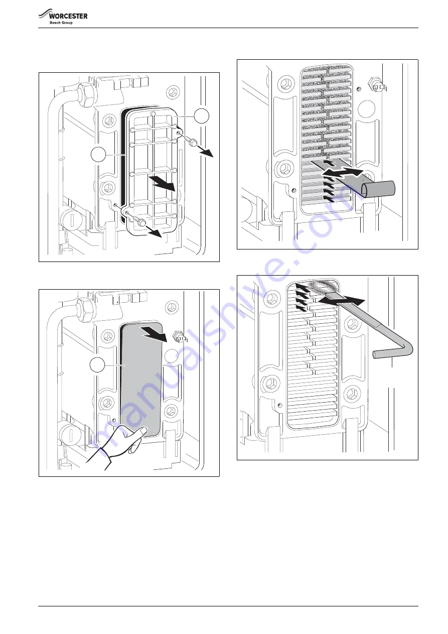
If the Heat Exchanger requires cleaning:

▶ Remove the condensate trap.
▶ Remove the cleaning access cover [1] and seal [2].

Fig. 51 Remove cover

▶ Press at the bottom to remove the metal plate [3], if fitted.

Fig. 52 Remove metal plate

▶ Using the cleaning blade, working from the bottom to the top, to 

loosen any deposits in the heat exchanger. 

Fig. 53

▶ Using the brush, clean the heat exchanger from top to bottom.

Fig. 54

▶ Use the handle of the brush to remove debris from the condensate 

tray.

▶ Place a suitable container under the sump condensate outlet to 

collect any water and debris.

6720818079-17.1Wo

1

2

6720818079-18.1Wo

3

6720818079-23.1Wo

6720818079-20.1Wo

Summary of Contents for GREENSTAR HIGHFLOW 440CDI ERP

Page 1: ...665 00 1Wo For sealed central heating systems and mains fed domestic hot water 6 720 818 077 2016 04 The appliances are for use with Natural Gas or L P G Cat II 2H3P type C13 C33 C53 Natural Gas Highf...

Page 2: ...r treatment 27 5 4 Starting the appliance 27 5 4 1 Switching the appliance on off 27 5 4 2 Initialization 28 5 4 3 Display messages 28 5 5 Checking gas inlet pressure 28 5 5 1 Measuring the inlet pres...

Page 3: ...used symbols These instructions are applicable to the Worcester appliance model s stated on the front cover of this manual only and must not be used with any other make or model of appliance These in...

Page 4: ...repairs must only be performed by a competent registered gas engineer such as a Gas Safe registered engineer or British Gas engineer Advisetheusertohavethesystemservicedannuallybyacompetent registered...

Page 5: ...28mm R1 BS5546 Installation of gas hot water supplies for domestic purposes EN12828 Central heating for domestic premises BS5440 1 Fluesandventilationforgasappliancesofratedheatingnot exceeding 70kW n...

Page 6: ...eat exchanger STANDARD PACKAGE Fig 1 Standard package 1 Floor standing gas fired combination boiler for central heating and domestic hot water 2 Mounting frame complete with pre plumbing manifold asse...

Page 7: ...ow rate Max 10 minutes from lighting The Gas Rate provided assumes the accepted NG averaged CV of 1040Btu ft3 38 76Mj m3 Natural gas network gas m3 h 3 19 4 29 Test gas G20 1014Btu ft3 37 78MJ m3 m3 h...

Page 8: ...for condensing boilers 30 C for low temperature boilers 37 C and for other heaters 50 C return temperature at heater inlet P1 kW 9 6 9 6 10 0 10 0 Useful efficiency At rated heat output and high tempe...

Page 9: ...i ErP 9 2 4 Layout and components Fig 2 Appliance layout 1 2 3 4 5 6 max 2 3 1 0 4 bar reset eco 1 2 3 4 e 6 max min 2 3 4 5 8 6 7 13 12 11 10 9 14 1 30 31 32 33 34 35 37 36 29 38 28 20 22 21 23 24 25...

Page 10: ...flow sensor turbine 20 Boiler tank drain connection point for filling loop 21 DHW Temperature sensor 22 CH Flow isolation valve 23 DHW Outlet 24 Gas isolation valve 25 Mains water inlet isolation valv...

Page 11: ...to BS EN50525 External 3A fuse to BS1362 The appliance must be earthed This appliance must not be connected to a three phase supply IPX4D The wiring between the appliance and the electrical supply mu...

Page 12: ...sel 2 must be fitted as close as possible to the appliance in the central heating return Pressurise the extra expansion vessel 2 to the same value as the built in expansion vessel refer to table 6 Tec...

Page 13: ...a minimum and any internal burrs on cut pipe work should be removed so that the internal pipe section is as smooth as possible Fitting an external air break Refer to figure 8 when a rain water down pi...

Page 14: ...EN 1451 The connection to the PRV must be made in copper pipe Plastic pipework must be properly supported with a maximum 300 mm between supports to prevent sagging and run downwards away from the boil...

Page 15: ...e boiler space by a non combustible partition as described in BS 6798 Fig 13 Airing cupboard clearances 3 6 3 Vented compartments If the clearances available are less than those stated for an unventil...

Page 16: ...e accessible provision must be made for service and inspection Voids containing concealed flues must have at least one inspection hatch no less than 300mm square Flue joints within the void must not b...

Page 17: ...NSTALLATION 6720818077 2016 04 Greenstar Highflow CDi ErP 17 350 mm 570 mm Flat roof 300 mm 500 mm Pitched roof 120 mm 120 mm 2 3 4 5 6 10 9 8 7 1 L L L L L L L L L L 6720648568 17 1Wo 120 mm 120 mm 1...

Page 18: ...0mm to room sealed flue or 1 500 to an open flue 15 200mm below eaves and 75mm below gutters pipe and drains 16 The dimension below eaves balconies and car ports can be reduced to 25mm as long as the...

Page 19: ...ny or overhang 9 1 200mm from an opening in a car port on the same wall e g door or window leading into the dwelling 10 600mm distance to a surface facing a terminal unless it will cause a nuisance BS...

Page 20: ...mage the panels or the floor Slide the boiler off the pallet Pull the plastic strip plug 6 down to remove from the boiler pipe work GENERAL HANDLING GUIDELINES Lift only a manageable weight or ask for...

Page 21: ...e 2 Manifold connections 3 Mounting frame fixing point 4 Wall 5 Gas and water pipe work not supplied 6 Boiler 4 3 Flue opening location Follow the figure 21 page 22 to mark the centre of the flue 1 2...

Page 22: ...is Floor standing boiler NOTICE FLUE LENGTH Do not exceed the maximum straight length for a horizontal or vertical flue or a 60mm plume management system if used as stated in the relevant Installation...

Page 23: ...r of debris and manoeuvre the boiler rear wheels onto the outer rails of the mounting frame 6 Take care when moving the boiler to position the front wheels onto the rails and align the gas water conne...

Page 24: ...and Safety Executive guidance HSG85 UsingtestequipmentapprovedtoGS38confirmthat the electricity supply is disconnected The mains electrical supply to the boiler and system wiring centre must be commo...

Page 25: ...imer ST10 Remove link Connect room thermostat LIVE supply to terminal LS Connect room thermostat LIVE return to terminal LR Connect room thermostat NEUTRAL to terminal NS Connect EARTH wire to the ear...

Page 26: ...lling loop Refit tank drain cap The Automatic Air Vent will release any air trapped in the boiler Vent all radiators retighten the vent when completed Check the system and correct any leaks Fig 32 Int...

Page 27: ...ppliance on off Turn on mains power supply Fig 34 3 Amp fused double pole isolator Turn on any external controls Set the TRV controls to maximum Set the clock programmer to continuously ON and the roo...

Page 28: ...n except reset button Key acknowledgement after pressing two buttons simultaneously Table 14 Special display messages 1 2 3 4 5 6 max 2 3 1 0 4 bar 1 reset eco 1 2 3 4 e 6 max min 6720818977 15 1Wo 10...

Page 29: ...mode the control will return to normal operation after 15 minutes Re seal the screw in the gas inlet pressure test point 5 5 2 Checking the gas rate The gas rate should be measured at the gas meter af...

Page 30: ...st have been calibrated as specified by the manufacturer Theinstallermustbecompetentinthe use of the analyser Check and zero the analyser in fresh air as specified by the manufacturer The air gas rati...

Page 31: ...how signs of leakage Refill and re pressurise if applicable as described in Commissioning 4 Operate the appliance and take note of any irregularities Call up the last fault stored by the Bosch Heatron...

Page 32: ...Fig 44 Access for servicing 6 4 Fan pressure test Remove the test point cover Connect a manometer to the fan pressure test point 1 Set the boiler to maximum output After measurement replace test poin...

Page 33: ...r button for more than 10 seconds Turn the temperature control to maximum and the boiler will go to maximum output Run the boiler at maximum output for at least 10 minutes After 10 minutes check the C...

Page 34: ...ction Angle the trap backwards and remove from the boiler Release the cap and dispose of the debris into a suitable container Replace the cap Before replacing the trap fill with at least 250ml of clea...

Page 35: ...fitted Fig 52 Remove metal plate Using the cleaning blade working from the bottom to the top to loosen any deposits in the heat exchanger Fig 53 Using the brush clean the heat exchanger from top to b...

Page 36: ...the air gas ratio To set the maximum CO2 To adjust the CO2 it will be necessary to first operate the boiler at maximum output Press and hold down the Service engineer button 1 for 10 seconds Turn temp...

Page 37: ...cehasstopped and remove the hose Fig 58 Draining the boiler GAS TYPE CO2 setting max CO2 setting min The CO2 should be measured after 10 minutes Greenstar HF 440CDi ErP Natural Gas 9 4 0 2 8 6 0 2 LPG...

Page 38: ...lower pipe union on gas pipe 5 Remove pipe 5 by pushing upwards and towards the rear of the boiler Twist the mixer unit 4 with gas pipe 5 to separate from the fan 1 Remove flap valve 6 from within fa...

Page 39: ...t electrical plugs 1 and 2 Remove the four Allen screws 6 and pull the pump head off Re assembly is a reverse of this procedure Fig 63 Pump and pump head removal 6 9 8 Sample points Air sampling point...

Page 40: ...Unplug the connection to the pressure relief valve Release the pressure gauge from the clips on the rear of the control panel 6 9 12 Expansion vessel Drain the appliance Move the control panel into s...

Page 41: ...ove the clips 3a castellated nuts 3b and springs 3c from the studs 3 Remove the nut 4a from the rear stud 4 Disconnect the mixer unit from the fan Remove the connector and earth wire from the fan Remo...

Page 42: ...Flow NTC 8 714 500 087 0 GC No E74 536 Heat exchanger overheat stat 8 714 500 056 GC No H08 291 DHW NTC 8 716 142 302 0 GC No 375 696 Tank NTC 8 716 142 319 0 GC No 379 785 Tank OH stat 8 716 103 217...

Page 43: ...l Live Neutral Live Colour sequence 7 8 9 B B 4 2 1 A F PRE WIRED LINK Wall plate contacts for Sense controls B B DHW TEMPERATURE CONTROL Earth PUMP SUPPLY FAN Colour sequence EXTERNAL FROST STAT OPTI...

Page 44: ...ax BURNER LIT YES NO YES YES GREEN LIGHT ON Burner stabilises at start speed for 5 10 seconds Fan reduces over 15 seconds Fan min speed for 90 seconds Boiler unused for long period Boiler operates to...

Page 45: ...tank temperature Is it still near set point GAS VALVE OFF Continue fan 40 seconds Continue pump 15 seconds Tank satisfied Modulate fan heat input to charge tank to temperature set by user control 65 7...

Page 46: ...od Internal boiler temperature rises above 12 C Central heating demand switches off Pump switches off after pump overrun period Central heating demand is activated Pump runs upto 3 minutes to dissipat...

Page 47: ...l connections of EMS controls if fitted connections on the control board replace control board b1 Code plug not detected Insert code plug correctly test and replace as necessary b2 b3 b4 b5 b6 Data er...

Page 48: ...s Cause Solution Green Red Off Off Mains supply not connected Power failure Connect mains supply Check mains and fuse circuit breaker Flashing Flashing Dry run possible air in pump Pump restarts autom...

Page 49: ...6720818077 2016 04 Greenstar Highflow CDi ErP 49 Notes...

Page 50: ...d 1RW UHTXLUHG RLOHU LQWHUORFN 3URYLGHG ALL SYSTEMS 7KH V VWHP KDV EHHQ XVKHG DQG FOHDQHG LQ DFFRUGDQFH ZLWK 6 DQG ERLOHU PDQXIDFWXUHU V LQVWUXFWLRQV Yes KDW V VWHP FOHDQHU ZDV XVHG KDW LQKLELWRU ZDV...

Page 51: ...SKRQH 1R DV VDIH UHJLVWHU 1R 5HFRUG W PD UDWH 2 SSP AND 2 W PLQ UDWH KHUH 3RVVLEOH 2 SSP AND 2 RPPHQWV 6LJQDWXUH SERVICE 04 DWH QJLQHHU QDPH RPSDQ QDPH 7HOHSKRQH 1R DV VDIH UHJLVWHU 1R 5HFRUG W PD UDW...

Page 52: ...orcester Bosch Group is a brand name of Bosch Thermotechnology Ltd worcester bosch co uk 6 720 818 077 2016 04 WORCESTER BOSCH GROUP TECHNICAL SUPPORT 0330 123 3366 APPOINTMENTS 0330 123 9339 SPARES 0...

Reviews: