


6-720-611-730b (12.05)
INSTRUCTION MANUAL
INSTALLATION COMMISSIONING
& SERVICING
GB/IE
THE APPLIANCE IS FOR USE WITH
NATURAL GAS OR L.P.G. (Cat II 2H3P TYPE C13 & C33)
NATURAL GAS (G20) : GC NUMBER 47-311-82
LIQUID PETROLEUM GAS (G31) : GC NUMBER 47-311-83
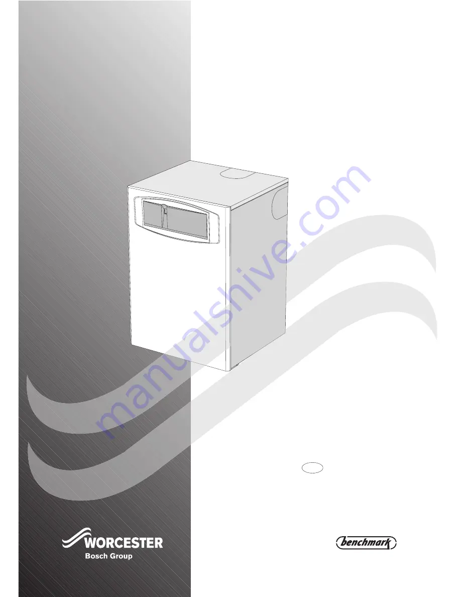
GREENSTAR HIGHFLOW 440
FLOOR STANDING RSF GAS-FIRED COMBINATION BOILER
FOR SEALED CENTRAL HEATING SYSTEMS AND MAINS FED DOMESTIC HOT WATER