background image

18

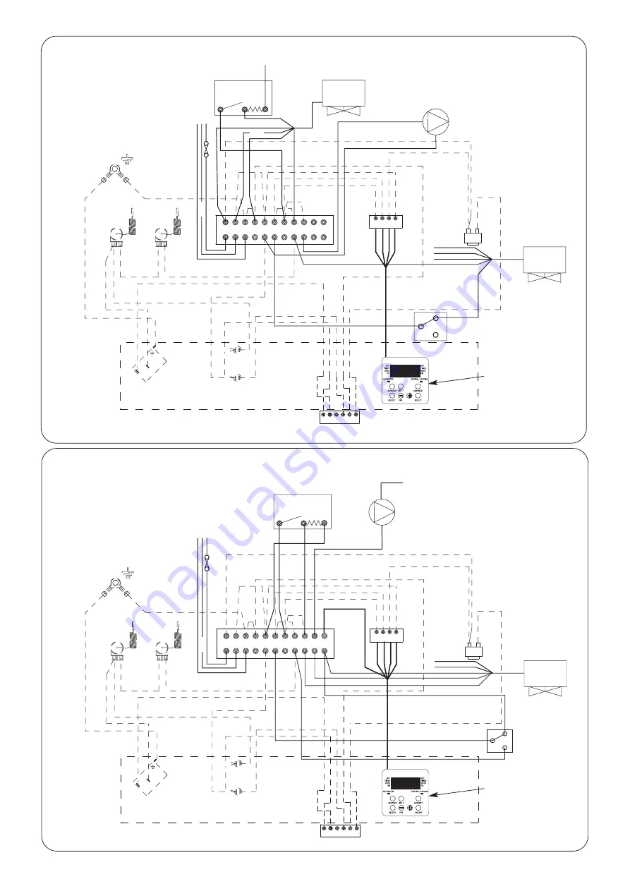
Fig. 19. 3 Port Valve Control Set.

NOTE:

When using a

Worcester programmer
remove the orange wire from
terminal 9 and connect to ter-
minal 6. Set the pin on the
rear of the programmer to
‘Pumped’. Remove link 1 to 3
and link 2 to 4 and make link
3 to 5.

Room thermostat

Pump

N

E N L

Burner Socket

Optional
Worcester
Programmer

Cylinder
Thermostat

C

1

2

Mid Position Valve
Honeywell V4073A

L N E E N 1

2

3 4

5

6

7 8 9

1112 

10

Blue

Brown

Green/Yellow

Blue

Grey

Orange

Orange

Grey

Green/Yellow

Brown

White

Brown

Blue

White

E

N

Blue

Fig. 18. 2 Port Valve Control Set.

NOTE:

When using a

Worcester programmer set
the pin on the rear of the pro-
grammer to ‘Pumped’.
Remove link 1 to 3 and link 2
to 4 and make link 3 to 4.

Room thermostat

Pump

N

E N L

Burner Socket

Optional
Worcester
Programmer

Cylinder
Thermostat

Hot Water Valve
Honeywell V4043H

L N E E N 1

2

3 4

5

6

7 8 9

1112 

10

Brown

Green/Yellow

Blue

Grey

Orange

Green/Yellow

Brown

Brown

L

E

N

Blue

Orange

Blue

Blue

Grey

Brown

Heating Valve Honeywell V4043H

Summary of Contents for DANESMOOR FS12/18

Page 1: ...ating 12 18 MINIMUM 12 kW 41 000 Btu h MAXIMUM 18 kW 61 500 Btu h 18 25 MINIMUM 18 kW 61 500 Btu h MAXIMUM 25 kW 85 000 Btu h THESE INSTRUCTIONS APPLY TO UK MODELS ONLY THESE INSTRUCTIONS ARE TO BE LEFT WITH THE APPLIANCE Patents Pending Boiler Application No 0203466 8 Baffle Application No 0303731 4 Burner Silencer Application No 0317154 3 Worcester supports the Benchmark code of practice ...

Page 2: ...he time of installation It confirms that the boiler has been installed and commissioned according to the manufacturers instructions Without the completion of the Log book manufacturers may refuse to respond to a call out from a householder who will be advised that he or she must call back the installer who has not fulfilled his obligations to record the information required by the initiative It is...

Page 3: ...BSP FUEL LINE 10 mm Compression MINIMUM FLUE REQUIREMENT CF 100 mm 4 in RS HEARTH TEMPERATURE Below 100 C MAXIMUM STATIC HEAD 30 m 98 ft PRIMARY WATER CAPACITY 20 5 litres WEIGHT 105 Kg 108 Kg BURNER Bentone Sterling 35 Bentone Sterling 40 WATER SIDE RESISTANCE 10 C Difference 40 mbar 77 mbar WATER SIDE RESISTANCE 20 C Difference 16 mbar 20 mbar EXIT FLUE GAS MASS FLOW 35kg hr 43kg hr SEDBUK RATIN...

Page 4: ...hat the air is adjusted to give the correct CO2 value NOTE The nozzle type used on 28 Sec Kerosene outputs are nozzles calibrated specifically for use with 28 Sec Kerosene which gives less variation in nozzle output than the standard 35 Sec Gas Oil nozzles However if a 28 Sec Kerosene nozzle is not available at servicing or commissioning it is appropriate to install a 35 Sec Gas Oil nozzle providi...

Page 5: ...e on the base of the side panels as shown in Fig 2 OPEN FLUE MODEL CF 6 1 In order to ensure clean and efficient combustion an adequate supply of air must be delivered to the combustion chamber To provide sufficient air a suitable inlet should be provided into the room or space in which the boiler is situated the sizes of which are given in Table 4 An air brick or other form of continuous air supp...

Page 6: ... Short user instructions located in slot provided in the fascia panel Burner seal gasket Silencer remove for RS Side panel locating lugs Side panel screw A Sample point Burner lockout reset button Manual reset thermostat button Side panel screw B Leading edge Control box assembly Control thermostat phial Automatic reset overheat thermostat phial Manual reset high limit thermostat phial Split pin ...

Page 7: ...nation The natural flue draught must be checked in the flue pipe imme diately above the appliance or in the hole provided in the flue outlet plate The flue draught should be no less than 0 75 mm W g and no greater than 5 1 mm W g If a flue draught greater than 5 1 mm W g is experienced a draught stabiliser should be introduced into the flue and adjusted to achieve a flue draught within the specifi...

Page 8: ...nal Not allowed 1200 K Vertically from a terminal on the same wall Not allowed 1500 L Horizontally from a terminal on the same wall Not allowed 750 M Above an intersection with the roof 600 Not applicable N From a vertical structure on the side of the terminal 750 Not applicable O Above a vertical structure less than 750mm from the side of the terminal 600 Not applicable P From a ridge terminal to...

Page 9: ...diameter can be determined using Tables 7 8 and 9 depending on whether a single or double pipe system or single pipe system with de aerator is being installed Selection of the correct pipe diameter will depend on the position of the oil stor age tank relative to the burner and the length of the pipe run b The oil supply pipe should be laid as level as possible to avoid air pockets and unnecessary ...

Page 10: ...ximum oil level H 4 m 13 ft maximum Fire valve to BS 5410 Fire valve to BS 5410 Isolating valve Isolating valve Fire detection element Filter Burner Burner Wall Wall b Double pipe system Isolating valve Non return valve Non return valve Fire detection element Isolating valve Oil tank c Single pipe lift system with de aerator Fire valve to BS 5410 H 3 5 m 11 5 ft maximum Burner Wall Fire detection ...

Page 11: ...ontrol Set Open Vent Fully Pumped System Feed and Vent Cistern Diverting valve Boiler Radiator S H Minimum static head 1m 3ft mea sured from the top surface of the appli ance or highest point in the heating sys tem to the water level in the feed and expansion tank N B A drain cock should be installed at the lowest point of the heating circuit Domestic hot water cylinder S H S H Automatic bypass va...

Page 12: ...1 2 Port Valve Control Set Open Vent Fully Pumped System Feed and Vent Cistern Central Heating valve Boiler Radiator S H Minimum static head 1m 3ft mea sured from the top surface of the appli ance or highest point in the heating sys tem to the water level in the feed and expansion tank N B A drain cock should be installed at the lowest point of the heating circuit Domestic hot water cylinder S H S...

Page 13: ...m Thermostat Primary cold feed 15mm min Heating vent 22mm min Fig 13 Semi Gravity Control Set Feed and Vent Cistern Hot Water valve Boiler Radiator S H Minimum static head 1m 3ft mea sured from the top surface of the appli ance or highest point in the heating sys tem to the water level in the feed and expansion tank N B A drain cock should be installed at the lowest point of the heating circuit Do...

Page 14: ... The first metre of pipework from all appliance connections must be in copper afterwards copper or plastic pipe can be used The plastic pipe must be manufactured to BS 7291 and installed to BS 5955 part 8 It is important to protect the system components the plastic pipe specified must be resistant to the ingress of oxygen 2 Feed and Expansion System The feed and expansion pipes must rise continuou...

Page 15: ... be fitted instead of an external programmer to the remote junction box Remove the link plug 8 to 9 and connect the programmer plug into the time clock connector Connect terminal 1 from the boiler termi nal block to the HOT WATER ON on the remote 10 way junction box Connect terminal 2 from the boiler terminal block to the HEATING ON on the remote 10 way junction box NOTE A 3 port valve control set...

Page 16: ... Brown Brown Green Yellow Earth Stud Manual reset thermostat Time clock connecter High limit thermostat Control thermostat Demand neon Lockout neon 5 Amp Blue Blue Green Yellow Green Yellow Plug in connector E Control box Satronic DKO 970 Green Yellow Green Yellow White Grey Red Black 1 2 3 4 5 6 7 8 9 Black Red Grey Lockout reset connector Brown Brown Orange 1 C Blue Blue White Grey L N E E N 1 2...

Page 17: ...Worcester programmer set the pin on the rear of the programmer to Pumped Remove link 1 to 3 Optional Worcester Programmer 10 WAY JUNCTION BOX NOTE If a frost thermostat is required it can be wired to the remote junction box NOTE The 10 way junction box must be a terminal block type and current rated to at least 5 amps Remote Pre wired Junction Box OUTSIDE BOILER INSIDE BOILER Green Yellow Blue Bro...

Page 18: ...3 4 5 6 7 8 9 1112 10 Blue Brown Green Yellow Blue Grey Orange Orange Grey Green Yellow Brown White Brown Blue White E N Blue Fig 18 2 Port Valve Control Set NOTE When using a Worcester programmer set the pin on the rear of the pro grammer to Pumped Remove link 1 to 3 and link 2 to 4 and make link 3 to 4 Room thermostat Pump N EN L Burner Socket Optional Worcester Programmer Cylinder Thermostat Ho...

Page 19: ...e rear of the programmer to Pumped Remove link 1 to 3 and link 2 to 4 Room thermostat Burner Socket Hot Water Valve Honeywell V4043H1106 Pump N ENL L N E E N 1 2 3 4 5 6 Cylinder Thermostat Blue Brown Brown Orange Grey Blue Green Yellow 7 8 9 11 12 10 L N E Optional Worcester Programmer White ...

Page 20: ... follow the procedure as for a double pipe system as described below NOTE This method may not be possible on some installations where a sub gravity system is used Where this problem arises bleed the system using the oil pump as described in Section 12 remove and clean the oil pump filter to remove debris collected as a result of installation b Double pipe system oil return pipe 1 Fit the double pi...

Page 21: ... Repeat the procedure until the burner fires and runs in a steady state On long oil pipe runs from the oil tank to the boiler it is recommend ed that the de aerator be primed to prevent damage to the oil pump To prime the de aerator follow the following procedure a Disconnect the flexible oil inlet hose end nearest the de aerator and place in a container of oil b Place an empty container to collec...

Page 22: ...p Lockout reset button Output Combustion Head Dimension kW A 12 18 PL 6 7 21 5 10 x 78 mm 5mm 18 25 PL 6 7 21 5 10 x 78 mm 5mm Combustion Head Draught tube Nozzle Nozzle block Air adjustment screw 4mm hexagonal head Spark gap 2 5 3 0mm 0mm 7 5mm A Pressure gauge port Transformer Fig 23 Baffle Arrangements 12 18 model 18 25 model Baffles Baffle retainer ...

Page 23: ...ng instructions 14 2 Pre Service Check 1 Remove the front panel by pulling the bottom of the panel forwards to release the ball studs and lifting the panel upwards and forwards to release from its supporting ledge 2 Operate the appliance and system noting any faults which may need to be corrected during the service 14 3 Cleaning the Burner 1 Check that the electrical supply to the appliance is swi...

Page 24: ...thoroughly clean in Kerosene or white spirit and re assemble into the filter 14 5 Clean the Boiler 1 Remove the access door by releasing the four M10 nuts and check the rope seal and insulation board Replace if necessary 2 Remove the baffle retainer as shown in Fig 23 3 Remove the baffles clean and check their condition Replace any baffles considered to be badly corroded or having insulation block...

Page 25: ...56 692 0 Control Box Base Satronic S01 S701 1 8 716 142 782 0 Ignition Electrode 1 8 716 142 752 0 Motor AEG FHP 90W 1 8 716 156 645 0 Oil Pump 1 Danfoss BFP41L3 1 8 716 142 743 0 Oil Pump 2 Suntec AS47C 1 8 716 157 014 0 Transformer Danfoss EBI 052F0030 excludes cable 1 8 716 156 696 0 Mechanical Shut Off Valve 1 8 716 156 658 0 Flexible Oil Line Kit Worcester 1 8 716 156 663 0 Burner O Shaped Ga...

Page 26: ...iler does not respond to a call for heat Boiler thermostat faulty Check by linking out high limit and control thermostats Programmer open circuit Check by linking 8 and 9 on the connector Faulty control box Replace if necessary Flue draught incorrect Check flue draught Combustion settings incorrect Set up as in installation instructions Faulty nozzle Replace nozzle HIGH SMOKE NUMBER Incorrect comb...

Page 27: ...27 ...

Page 28: ...t All goods sold are subject to our official Conditions of Sale a copy of which may be obtained on application PUBLICATION 8 716 115 036a 05 08 Bosch Group Worcester Bosch Group Cotswold Way Warndon Worcester WR4 9SW Telephone 01905 754624 Fax 01905 753130 Technical Helpline 08705 266241 Worcester Bosch Group is a trading name of BBT Thermotechnology UK Limited www worcester bosch co uk ...

Reviews: