


12
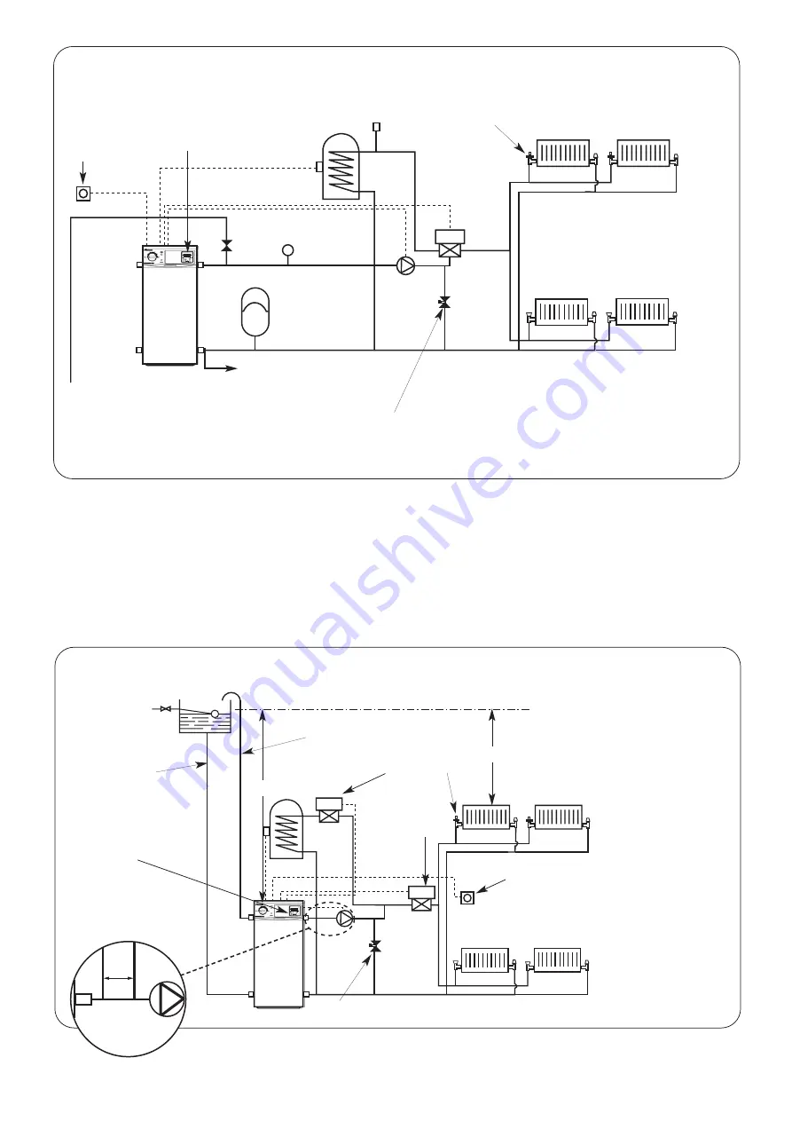
Automatic
air vent
Fig. 10. 3 Port Valve Control Set (Fully Pumped Sealed System).
Expansion
Vessel
Diverting
valve
Pump
Radiator
N.B.
A drain cock should be
installed at the lowest point of
the heating circuit
Domestic hot
water cylinder
Pressure
gauge
Safety valve
To system filling device (see Fig.14)
Boiler
Automatic bypass valve to be fitted
where thermostatic radiator valves
are fitted on all radiators
Fascia mounted twin channel
programmer
T.R.V
Primary cold
feed (15mm min.)
Heating vent
(22mm min.)
Fig. 11. 2 Port Valve Control Set (Open Vent Fully Pumped System).
Feed and
Vent Cistern
Central Heating
valve
Boiler
Radiator
S.H. – Minimum static head 1m (3ft) mea-
sured from the top surface of the appli-
ance or highest point in the heating sys-
tem to the water level in the feed and
expansion tank
N.B.
A drain cock should be
installed at the lowest point of
the heating circuit
Domestic hot
water cylinder
S.H.
S.H.
Automatic bypass valve to be fitted where thermostatic radiator
valves are fitted on all radiators
Primary cold
feed (15 mm)
Heating vent
(22 mm min)
Pump
T.R.V
Room
Thermostat
Room
Thermostat
Hot Water
valve
Fascia mounted twin channel
programmer
150mm
(max)
Feed
(15mm)
Vent
(22mm)
Optional Feed and Vent Supply
Summary of Contents for DANESMOOR FS12/18
Page 27: ...27 ...


