background image


We appreciate your comments about the content of our publications. 

Send comments to: 

[email protected]


Please reference publication 

04176G

.


ËB04176:G´ºµ¹´¹Î


PO Box 1519, Fort Collins CO 80522-1519, USA 

1000 East Drake Road, Fort Collins CO 80525, USA 

Phone +1 (970) 482-5811 

 Fax +1 (970) 498-3058 

Email and Website—

www.woodward.com


Woodward has company-owned plants, subsidiaries, and branches, 

as well as authorized distributors and other authorized service and sales facilities throughout the world. 

Complete address / phone / fax / email information for all locations is available on our website. 


Summary of Contents for ProAct II

Page 1: ...Product Manual 04176 Revision G 8 2015 Original Instructions ProAct II Electric Powered Actuator and Driver Installation and Operation Manual...

Page 2: ...amage to the equipment Any such unauthorized modifications i constitute misuse and or negligence within the meaning of the product warranty thereby excluding warranty coverage for any resulting damage...

Page 3: ...ronic Circuits 18 Actuator Position Signal 19 Actuator 19 CHAPTER 4 TROUBLESHOOTING 20 Linkage and Actuator Stroke 20 CHAPTER 5 TECHNICAL SPECIFICATIONS 21 Power Supply 21 Actuator Position Feedback 2...

Page 4: ...ator 8 Figure 1 4 Plant Wiring Diagram 9 Figure 2 1 Diesel Engine Travel Stops 12 Figure 2 2 Carburetor Travel Stops 12 Figure 2 3 ProAct II Mounting Bracket 12 Figure 2 4 Preparing Shielded Wiring 13...

Page 5: ...mover control system An overtemperature or overpressure shutdown device may also be needed for safety as appropriate Personal Protective Equipment The products described in this publication may prese...

Page 6: ...sed by improper handling read and observe the precautions in Woodward manual 82715 Guide for Handling and Protection of Electronic Controls Printed Circuit Boards and Modules Follow these precautions...

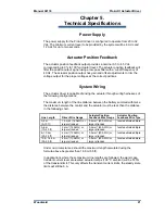
Page 7: ...ct II drivers require a separate electrical supply of 20 32 Vdc The supply must be capable of providing a sustained 6 A and a peak 12 A for up to two seconds for the driver The ProAct actuator provide...

Page 8: ...ProAct II Actuator Driver Manual 04176 6 Woodward Figure 1 1 Outline Drawing of ProAct II Driver with IP56 Box...

Page 9: ...Manual 04176 ProAct II Actuator Driver Woodward 7 Figure 1 2 Outline Drawing of ProAct II Driver with Sheet Metal Box...

Page 10: ...ProAct II Actuator Driver Manual 04176 8 Woodward Figure 1 3 Outline Drawing of ProAct Actuator...

Page 11: ...Manual 04176 ProAct II Actuator Driver Woodward 9 Figure 1 4 Plant Wiring Diagram...

Page 12: ...ng requirements in Chapter 5 The driver will generate some heat so surfaces must be open to normal air movement No special ventilation is required Ideally the driver should be mounted flush to the met...

Page 13: ...ge between the actuator and the fuel system Maximum actuator speed is 900 degrees per second in both the increase and decrease fuel directions The ProAct II actuator s Mass Moment of Inertia MMOI with...

Page 14: ...itude The actuator is weatherproof and resistant to the corrosive effects of water and salt water Avoid pressure washing near the shaft seals The ProAct II actuator weighs 6 9 kg 15 23 lbs The bracket...

Page 15: ...See Woodward application note 50532 Interference Control in Electronic Governing Systems for more information Where shielded cable is required cut the cable to the desired length and prepare the cabl...

Page 16: ...he minimum stop If the battery charging system is off when the engine is shut down this will cause the battery to be drained In this case the power to the ProAct must be turned off with a switch or re...

Page 17: ...Manual 04176 ProAct II Actuator Driver Woodward 15 Figure 2 5 Correct Wiring to Power Supply Figure 2 6 Incorrect Power Supply Wiring...

Page 18: ...2 7 for adjustment locations The procedure for adjusting the system position feedback is as follows To set up the driver system feedback first disconnect the actuator drive wires at the control DO NO...

Page 19: ...for adjustment locations To set up the driver and actuator power up the system with the actuator disconnected from the linkage but with the inertia disk in place DO NOT START THE ENGINE AT THIS TIME...

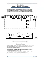
Page 20: ...ensor from the actuator Figure 3 1 Figure 3 1 ProAct II Functional Block Diagram Electronic Circuits All circuits in the ProAct driver are solid state and are not serviceable in the field The printed...

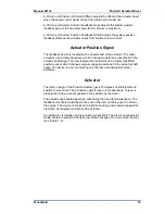
Page 21: ...tuators use a rotary Hall Effect position sensor which changes output voltage proportional to the actuator shaft angle The device is a non contacting unit thereby eliminating most wear problems Actuat...

Page 22: ...as possible Carefully follow the guidelines in the Actuator Installation section of Chapter 2 in making linkage arrangements Using less than optimum actuator movement will make stability more difficul...

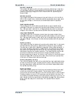
Page 23: ...tance between the battery summed with twice the distance between the control and the actuator must be less than the distance in the following chart Line Length Driver Wire Gauge Actuator Position Feed...

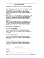
Page 24: ...of 0 to 4 V for all inputs The following items are not longer available 11 20 mA No longer available The 11 20 mA input will accept a 0 to 20 mA dc input The nominal input of 12 to 20 mA will corresp...

Page 25: ...travel after the unit has been calibrated to the actuator for gain and offset This accuracy is valid at the calibration temperature of the actuator assembly If the actuator assembly temperature is di...

Page 26: ...also be handled through the OEM or Packager Please review your equipment system documentation for details Woodward Business Partner Support Woodward works with and supports a global network of indepe...

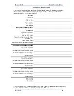
Page 27: ...option is applicable to mechanical products only Returning Equipment for Repair If a control or any part of an electronic control is to be returned for repair please contact your Full Service Distrib...

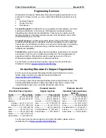
Page 28: ...mation on these services please contact one of the Full Service Distributors listed at www woodward com directory Contacting Woodward s Support Organization For the name of your nearest Woodward Full...

Page 29: ...pe of Fuel gas gaseous diesel dual fuel etc Power Output Rating Application power generation marine etc Control Governor Information Control Governor 1 Woodward Part Number Rev Letter Control Descript...

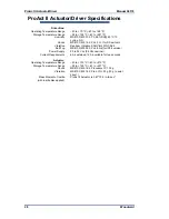
Page 30: ...bration Random Vibration 0 04G Hz WGC RV2 Salt Fog MS810D M509 2 PL 48 hrs for IP56 version Power Supply 20 to 32 Vdc 24 Vdc nominal Current Requirements 6 A sustained 12 A available for two seconds A...

Page 31: ...Input Configuration table page 5 Marked Input Configurations 11 20 4 13 mA and 0 5 Volt as no longer available Page 22 Changes in Revision F Revision advanced to coordinate with new installation shee...

Page 32: ...ProAct II Actuator Driver Manual 04176 30 Woodward Declarations...

Page 33: ...9 USA 1000 East Drake Road Fort Collins CO 80525 USA Phone 1 970 482 5811 Fax 1 970 498 3058 Email and Website www woodward com Woodward has company owned plants subsidiaries and branches as well as a...

Reviews: