


MAINTENANCE
-30-
To replace the drive belts, do these steps:
1.
Lay the jointer on its side so the switch is
facing up.
2.
Remove the bottom cover.
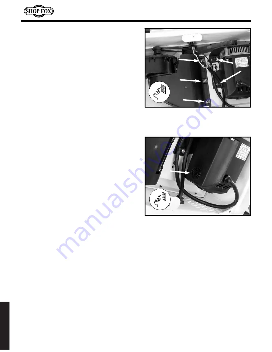
3.
Loosen the screws securing the motor
mount plate and the impeller mount plate
(
Figure 44
).
4.
Adjust the mounting plate to allow the drive
belts to loosen.
5.
Remove the drive belts.
6.
Replace or re-install the drive belts, making
sure they are aligned correctly.
7.
Replace the bottom cover.
To replace the drive belts, do these steps:
1.
Lay the jointer on its side so the switch is
facing up.
2.
Remove the bottom cover.
3.
Using a flat-head screwdriver, remove the
motor brush caps (
Figure 45
).
4.
Replace the motor brushes if they are dam-
aged or severely blackened by carbon build-
up.
5.
Re-install the motor brush caps.
6.
Replace the bottom cover.
Figure 44.
Motor and impeller
mount plate screws.
Figure 45.
Motor brush caps.
Motor Brushes
Drive Belts