background image

INSTALLATION

To install the Extension Block Kit, do these steps:

1.


Disconnect the bandsaw from the power source! 

2.

  Open the wheel covers and remove the blade per 

the directions in the Model W1706 Instruction 

Manual.

3.

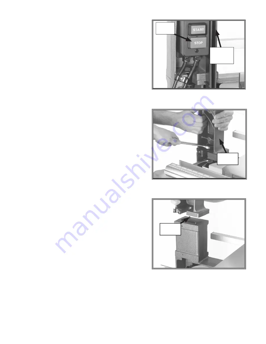
  Remove the left-side blade guard (

Figure 2

).

4.

  Remove the power switch assembly (

Figure 2

) by 

unscrewing two Phillips screws that mount the 

power switch assembly and the Phillips screw 

that mounts the wire clip below the assembly. 

Temporarily place the assembly to the side. DO NOT 

disconnect the wiring, and wait until 

Step 13

 to 

remove the guide post assembly.  

5.

  Have an assistant support the upper arm assembly, 

then loosen the nut, as shown in

 Figure 3, 

and slide 

the bolt out.

6.

  Remove the upper arm and set it aside. 


Note:

 The upper arm is pinned to the base. If 

removal is difficult, carefully rock the upper arm 

loose.

7.

  Place the extension block onto the base pins. 

8.

  Have an assistant place the upper arm onto the 

extension block pins, as shown in 

Figure 4,

 and hold 

the upper arm in place. 

9. 

Place a washer over the long bolt included with the 

extension kit and slide the bolt down through the 

extension block.

10. 

Attach the washer and the nut to the extension 

Figure 4. 

Placing upper arm on extension 

block.

Figure 3. 

Loosening bolt while an assistant 

supports the upper arm assembly.

Figure 2.

 Power switch and left side blade 

guard.

Left-side

Blade 

Guard

Power 

Switch

Upper 

Arm

Base 

Pin

Summary of Contents for SHOP FOX D3348

Page 1: ...ine when performing any maintenance or assembly Failure to do this may result in serious personal injury SUFFOCATION HAZARD Immediately discard all plastic bags and packing materials to eliminate choking suffocation hazards for children and animals Box Contents Figure 1 Figure 1 Main Contents A Extension Block 1 B Saw Blade 1 C Saw Blade Guard 1 D Guide Post 1 E Hex Bolt and Flat Washer 1 F Blade ...

Page 2: ...ort the upper arm assembly then loosen the nut as shown in Figure 3 and slide the bolt out 6 Remove the upper arm and set it aside Note The upper arm is pinned to the base If removal is difficult carefully rock the upper arm loose 7 Place the extension block onto the base pins 8 Have an assistant place the upper arm onto the extension block pins as shown in Figure 4 and hold the upper arm in place...

Page 3: ...tach the guide assembly see Figure 5 and the extended blade guard to the extended guide post 15 Install the 105 bandsaw blade tension it prop erly test the tracking and adjust the blade guides according to the manual instructions 16 Check the alignment of the bandsaw wheels accord ing to the manual and align if necessary 17 Replace the power switch assembly If you need additional help with this pr...

Page 4: ...FLAT WASHER 5 8 4A XPN04 HEX NUT 5 8 11 5 XD3348005 PIN 6 X 15 60A XD3348060A SAW BLADE 6 TPI X 105 X 3 8 65A XD3348065A SAW BLADE GUARD 84A XD3348084A GUIDE POST LONG 90A XD3348090A BLADE GUARD LONG 90B XD3348090B BLADE GUARD 152 XD3348005 EXTENSION BLOCK 162A XPCB02 CARRIAGE BOLT 5 16 18 X 1 2 164 XPW07 FLAT WASHER 5 16 165 XPWNO3 WING NUT 5 16 18 124A XD3348005 CORD CLAMP 125A XPS01 PHLP HD SCR...

Reviews: