


16
Close the casing and lock into place by turning the
•
screw of a revolution to the right.
When the cover is closed, read the adjusted speed from
•
the viewing-window.
When working with highly unbalanced workpieces, se-
•
lect a speed at least one level lower.
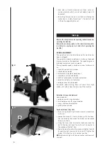
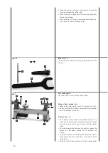
Driver, Fig. 1.2
The driver (A) is used exclusively for work between both
centers.
Face plate, figure 1
The face plate is used with flat larger tools.
Change of the clamping tools
Loosen grub screw on the shaft of the clamping tool.
•
Retain spindle with mandrel, release the clamping tool
•
with the hexagonal spanner.
Tailstock, Fig. 1, 6
Once the eccentric clamp has been loosened, the tail-
•
stock can be moved over the entire length of the bed
and can be secured at any distance from the head-
stock.
To insert a workpiece between the centers, loosen the
•
binder, turn the sleeve approx. 20 mm outward and
clamp.
Slide the tailstock to the workpiece and place the tail-
•
stock center into the sunken point in the center of the
workpiece.
Screw out the tailstock sleeve until the tailstock center
•
Fig. 1.2
C
A
D
B
1
2
3
4
5
6
7
8
9
10
Fig. 1