Assembly
37
MAN0632 (5/15/2007)
Figure 31
.
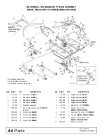
BB60X, BB72X
&
BB84X
Shipping Configuration
DISASSEMBLE SHIPPING UNIT
(FIGURE 32)
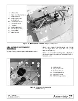
Remove all parts that are wired and strapped to cutter.
Remove cap screws (13) and flange lock nuts (14) that
are securing A-frame bars (2) to the cutting height
adjustment holes (10).
Remove cap screws (13) and flange lock nuts (14) that
are securing tailwheel bracket (6) and diagonal brace
bars (4) to cutter.
Figure 32
. Shipping Unit Disassembly
(
BB48X
Shown)
2. A-Frame bar
3. Upper mounting hardware
4. Diagonal brace
5A. Diagonal brace bar
mounting hole
5B. Tailwheel pivot hole
6. Tailwheel bracket
9. Tailwheel
10. Height adjustment
13. Driveline (Slip clutch)
14. Clutch shield
15. Rubber shield
15
5A
6
3
13
14
5B
2
10
4
9
13 14
6
13
14
4
2
2. A-Frame bar
4. Diagonal brace bar
6. Tailwheel bracket
10. Height adjustment
13. 5/8 NC x 2 HHCS
14. 5/8 NC Flange lock nut
13
14
10
(Rev. 5/10/2009)

