34 Assembly
MAN1339
(05/17/22)
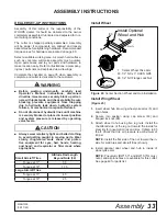
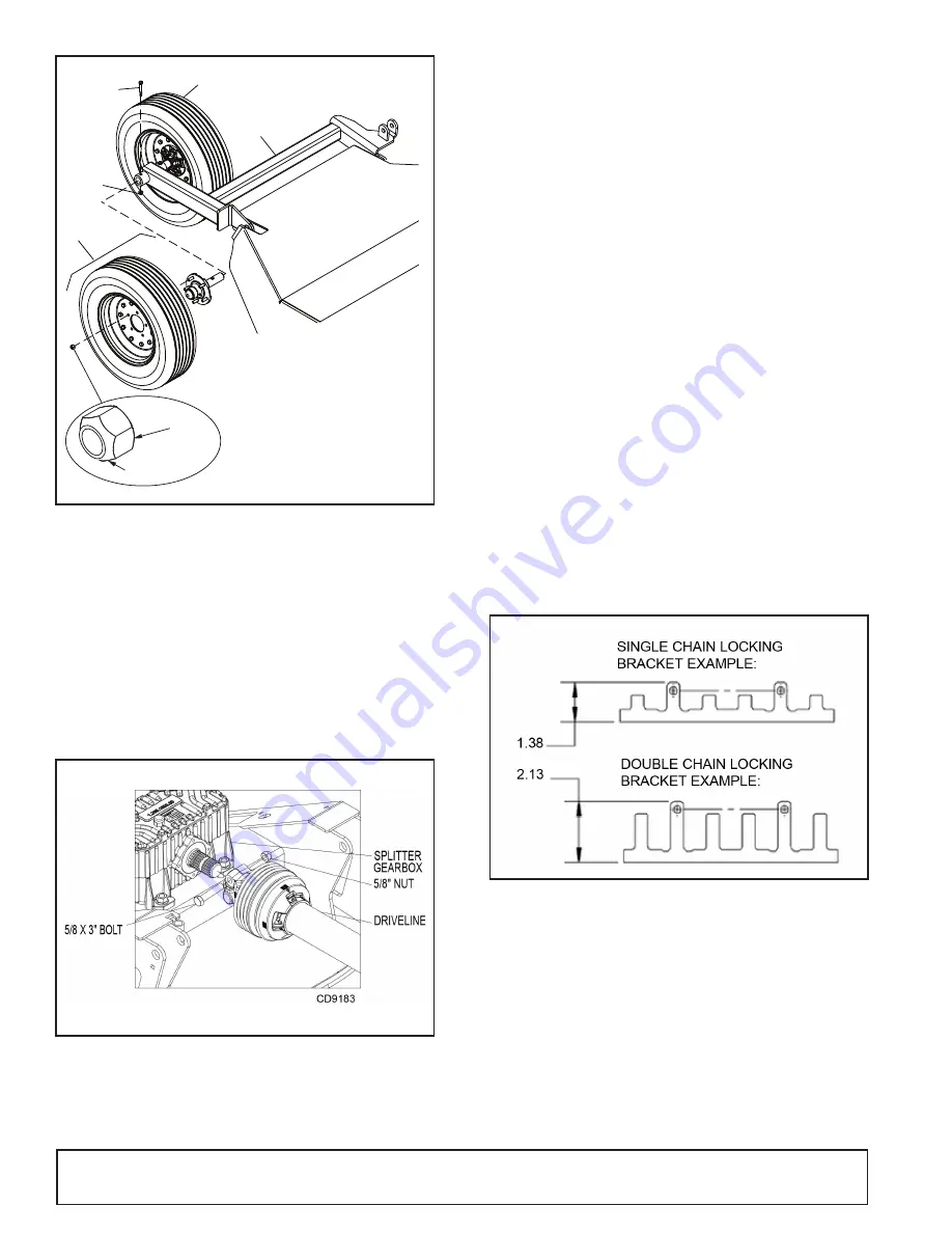
Figure 23.
Wing Wheel - Right
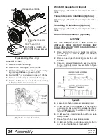
Install Driveline
1.
Remove driveline from wing.
2.
Remove 5/8" retaining bolt from driveline.
3.
Slide driveline yoke onto gearbox input shaft align-
ing retaining bolt hole to groove in shaft.
4.
Reinstall 5/8" bolt and nut and torque to 110 ft-lbs.
5.
Remove driveline shipping brackets from wing.
6.
Replace bolts and nuts in skid shoe with carriage
bolts and nuts found in manual tube.
Figure 24.
Driveline Installation
Winch Kit Installation (Optional)
Refer to page 57 for Installation and Operation instruc-
tions.
Tandem Axle Arm Installation (Optional)
Refer to page 58 for Installation and Operation instruc-
tions.
Shredding Kit Installation (Optional)
Refer to page 59 for Installation and Operation instruc-
tions.
Double Chain Installation (Optional)
DO NOT REMOVE SINGLE ROW CHAIN AS
INSTALLED FROM FACTORY. DOUBLE ROW
CHAIN KIT IS AN ADDITION TO STANDARD SINGLE
ROW CHAIN SHOWN.
1.
Raise unit to full height and install transport lock
pin. See page 17. Refer to page 19 for blocking
instructions.
2.
Remove one single chain locking bracket from unit
at a time.
3.
Compare removed bracket with new double lock
brackets to identify correct new part. Refer to Figure
25 for example.
Figure 25.
4.
Leave single chain in place except where noted.
5.
Install chain as shown in pages 51 & 52, doubling
over on center link and sliding over extended finger.
Center chain loop may be vertical or horizontal as
required for installation.
6.
Install new lock bracket and attach with new hard-
ware provided.
7.
Repeat for each individual locking bracket.
8.
Install rear chain flap on wing tail wheel arms if wing
arm has lug for attachment. See page 51.
NOTICE
Optional Wheel & Hub
58
88
5
Chamfer
Flat
CD6800-4
83
5. Wing wheel yoke arm,
right
58. Wheel and hub
83. 1/2 NC x 3 HHCS GR5
88. 1/2 NC Flanged lock nut

