


7. Once fuel has been loaded, close the door and
leave the air inlet control fully open until
fire
is well
established (at least 15–20 minutes) being careful
not to over
fire
(if any of the exterior parts of the
stove or chimney connections begin to glow you
are ov
er fi
ring the stove).
8. Re-adjust the primary air inlet control to the desired
burn rate. For “high” setting pull the primary air con
-trol (center control) all the way out, for “low” push all
the way back. (If excessive smoke
fills the fireb
ox,
open air inlet control slightly until
flames
resume
and wood is
sufficiently
ignited.) The basic rule of
thumb is “closed (push in) = low,” “half way open =
medium” and “fully open (pull out) = high.”
9.
CAUTION: Always be sure to securely close the
front door when you are satisfied with the quality
of the fire burn. Firmly rotate door handle counter
clock-wise until the handle stops rotation. Never
leave stove unattended with door open!
-
CAUTION: DO NOT OVER FIRE APPLIANCE.
YOU ARE OVER FIRING IF THE CHIMNEY
CONNECTORS OR STOVE GLOWS RED. CLOSE
THE DOOR AND IMMEDIATELY SHUT ALL AIR
CONTROLS (PUSH IN) TO REDUCE THE AIR
SUPPLY AND SLOW DOWN THE FIRE.
CAUTION: SLOW BURNING FIRES AND EXTEND-
ED USE MAY CAUSE EXCESSIVE CREOSOTE
BUILDUP. IGNITION OF CREOSOTE OR OVER
FIRING MAY CAUSE A CHIMNEY FIRE. CHIMNEY
FIRES BURN EXTREMELY HOT AND MAY IGNITE
SURROUNDING MATERIALS. IN CASE OF A
CHIMNEY FIRE CALL THE FIRE DEPARTMENT
IMMEDIATELY.
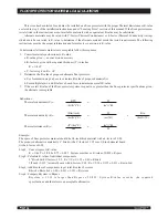
ADDING FUEL
If the coal bed is not hot and glowing, rake the coals
to the front of the stove, close the door and adjust the
primary air inlet control to the wide open position. Let
the coals re-heat for 10–15 minutes. When hot and
glowing, spread them out and place your next fuel load
into the stove (make sure no coals or ashes block the
LPAO). Leave the primary air inlet control in the wide
open (pulled out) position for 15–20 minutes.
Fuel load size can vary but should be kept
1–2˝
(25mm-50mm) below the secondary air tubes. Also
position the fuel to leave space so the air from the inlet
can work between the pieces of fuel. This reduces the
time it takes for new fuel to burn properly.
1. When refueling, increase the center primary air
control to the fully open (pulled out) position. When
fire
brightens, slowly and carefully open the door.
This procedure will prevent unburned gases from
igniting causing smok
e and flame spillag
e.
2. When adding fuel be careful not to hit, bump or
damage the secondary air tubes at the top of the
fireb
ox.
3. Add fuel being careful not to overload or over
fire
the stove.
4. When adding fuel be careful not to smother the
fi
re.
Do not build
fires
against glass and make sure the
coal bed does not obstruct the air inlet. Do not load
fuel to a height or in such a manner that it creates
a hazard when opening the door.
5. Close the feed door and secure tightly.
6. Adjust the air inlet control as described above.
7. Empty ashes regularly. Do not allow ashes
to pile up (see Safety Instructions #14
n
o
page 2.)
8. Properly dispose of hot ashes (see Safety
Instructions, item #14 on page 2.)
9. Do not over
fi
re the stove (over
fi
ring is when
any part of the stove exterior or chimney
connections glow).
CREOSOTE – FORMATION AND NEED FOR
REMOVAL
CAUTION: RISK OF FIRE When wood is burned
slowly, it produces tar and other organic vapors,
which combine with expelled moisture to form
creosote. The creosote vapors condense in the
relatively cool chimney
flue
of a slow-burning
fir
e. As a result, creosote residue accumulates
on the
flue
lining. When ignited this creosote
makes an extremel
y hot fir
e.
The chimney connector and chimney should
be inspected at least once every two months
during the heating season to determine if a
creosote buildup has occurred.
If creosote has accumulated (3mm or more)
it should be removed to reduce the risk of a
chimne
y fir
e.
Failure to remove creosote may result in ignition
and may cause a house/building
fir
e. Creosote may be
continued on next page
OPERATING INSTRUCTIONS
...continued
19
Summary of Contents for WS-TS-1500
Page 6: ...6 Minimum Clearances for installation according to UL 1482 US ULC S627 CAN A ...
Page 7: ...7 Top A A Alcove ...
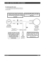
Page 8: ...philips BLOWER ATTACHMENT 8 4 places A GASKET ...
Page 9: ...9 WS TS 2500 23 8 6 ...
Page 10: ...10 6 ...
Page 20: ...20 ...
Page 21: ...21 ...
Page 23: ...23 BAFFLE REMOVAL ...
Page 24: ...24 BAFFLE REMOVAL ...
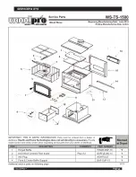
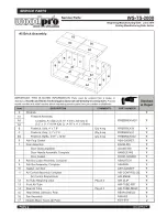
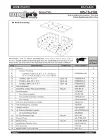
Page 25: ...SERVICE PARTS 25 ...
Page 26: ...SERVICE PARTS 26 ...
Page 27: ...SERVICE PARTS 27 ...
Page 28: ...SERVICE PARTS 28 ...
Page 29: ...SERVICE PARTS 29 ...
Page 30: ...SERVICE PARTS WS TS 2500 30 ...
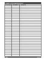
Page 33: ...DATE OF SERVICE PERFORMED BY DESCRIPTION CHIMNEY STOVE MAINTENANCE LOG 33 ...
Page 35: ...Warranty 35 ...
Page 36: ...36 www woodprostoves com 2 ...


