


CONNECTOR PIPE SIZING
Connector pipe is used to make the connection
from the
final
positioning of your stove to an approved
chimney. Connector pipe is
NOT
included
as part of
the stove. Connector pipe must be 6”/152mm diameter
minimum of 24 MSG (minimum standard gauge) b
la
ck
or 26 MSG b
lue steel st
ove pipe.
NOTICE: FOR MOBILE HOME INSTALLATIONS
(US ONLY), CONNECTOR PIPE MUST BE
DOUBLE-WALL, HIGH-TEMPURATURE PIPE
THAT MEETS UL 103 HT SPECIFICATIONS.
Any connector pipe used must be in good condition.
Rep
l
ace if necessary before using stove. Connector
pipe is not rated to provide c
l
ose contact to combustib
l
e
mater
ials
and must have proper
clea
rance from com-
bustib
le
mater
ials
as shown in the
clea
rance diagrams
on the previous pages. Connector pipe shou
l
d never be
used in p
l
ace of a chimney. If proper c
lea
rances are not
observ
ed a house fire could result.
INSTALLATION INSTRUCTIONS
Please Note: Insta
ll
ation of a
fl
ue damper is NOT
recommended. Combustion contro
l
is regu
l
ated by the
intake of combustion air, not the exhaust.
1. The crimped end of the stovepipe
fits
inside the
stove
fl
ue co
ll
ar. Secure with three (3) equa
ll
y
spaced sheet meta
l
screws. The
fi
rst section of
connector pipe must be
single
w
alled
to proper
ly
attach to the stove c
oll
ar. Insta
ll
additio
nal
pipe and
e
l
bow with the crimped end towards the stove. This
will
all
ow any condensation in the
flue
to run back
into the fireb
ox.
2. Horizonta
l
pipe runs must s
l
ope upwards
towards the chimney at
least
1/4˝/6.4mm
per foot
of horiz
ontal
run.
3. You must have at
least
18˝/457mm
of
clea
rance
between any horiz
ontal piping and the ceiling.
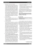
4. The pipe cannot extend into the chimney f
l
ue
(figure 8).
5. Secure a
ll
pipe/e
l
bow sections with three (3) equa
ll
y
spaced sheet
metal
screws at each joint to make
the piping rigid. DO NOT CONNECT THIS STOVE
TO ANY AIR DISTRIBUTION DUCT OR SYSTEM.
6. It is recommended that no more than two (2)
90° bends be used in the stovepipe insta
ll
a-
tion. The use of more than two 90° bends may
decrease the amount of draw and possib
l
y
cause smoke
spillag
e. Where possib
l
e, use
only
corrugated (non adjustab
l
e) e
l
bows. These
pro
vide a better seal.
7.
The connector pipe must not pass through an
attic or roof space, trusses, c
l
oset, or any concea
l
ed
space,
floo
r,
ceiling,
w
all,
or combustib
le
construc-
tion. (See Chimney Connector Systems &
Clear
-
ances, page
17.)
A manufactured chimney system
listed
to UL 103 HT (US)/ULC-S629 (CAN) must
be used from the
first
penetration of
ceiling
or w
all
to the chimney cap.
Where passage through a w
all
or partition of com-
bustib
l
e construction is desired, the insta
ll
ation sha
ll
conform to Chimney manufacturer’s instructions.
WARNING: DO NOT USE SINGLE WALL CON-
NECTOR PIPE AS A CHIMNEY - A HOUSE FIRE
COULD RESULT.
Figure 8 – S
tovepipe/Flue Connections
NOTE: CONNECTOR PIPE IS
NOT INCLUDED
.
TO PURCHASE, VISIT YOUR LOCAL HARD-
WARE, HOME, OR BUILDING CENTER.
ADDITIONAL SPECIFICATIONS.
11
Summary of Contents for WS-TS-1500
Page 6: ...6 Minimum Clearances for installation according to UL 1482 US ULC S627 CAN A ...
Page 7: ...7 Top A A Alcove ...
Page 8: ...philips BLOWER ATTACHMENT 8 4 places A GASKET ...
Page 9: ...9 WS TS 2500 23 8 6 ...
Page 10: ...10 6 ...
Page 20: ...20 ...
Page 21: ...21 ...
Page 23: ...23 BAFFLE REMOVAL ...
Page 24: ...24 BAFFLE REMOVAL ...
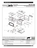
Page 25: ...SERVICE PARTS 25 ...
Page 26: ...SERVICE PARTS 26 ...
Page 27: ...SERVICE PARTS 27 ...
Page 28: ...SERVICE PARTS 28 ...
Page 29: ...SERVICE PARTS 29 ...
Page 30: ...SERVICE PARTS WS TS 2500 30 ...
Page 33: ...DATE OF SERVICE PERFORMED BY DESCRIPTION CHIMNEY STOVE MAINTENANCE LOG 33 ...
Page 35: ...Warranty 35 ...
Page 36: ...36 www woodprostoves com 2 ...


