


3
10
Place the arm plate
(1475A2)
with it’s groove covering
the threaded rod and fasten it to the adjuster arm using
the 3/4" screws
(5771B)
. Align the top and bottom edge
of both parts before tightening the screws.
See fig. 9.
Adjust the two nuts on the threaded rod, along with
the washers, against the underside of the adjuster arm.
Tighten the nuts against each other when you have adjusted
the up/down slop out of the height adjuster.
See fig. 9.
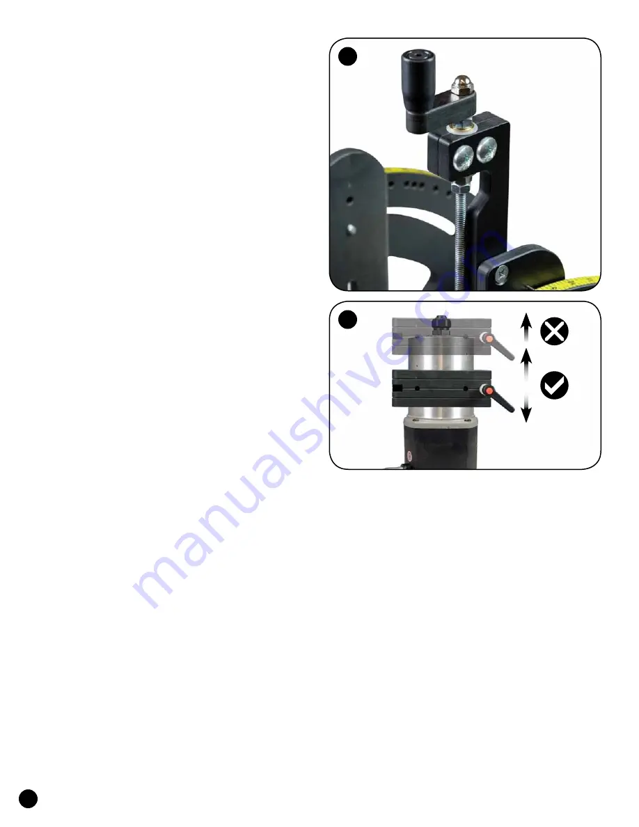
ROUTER INSTALLATION
Loosen the clamp handle in the router block and insert
your router in the router block so the end of the motor is flush
with the router block, or protruding out past it..
The router
motor should always be fully inserted in the router block!
Never insert a router motor partially in the router block!
The
router motor can be repositioned anywhere in the motor block as
long as it is completely in the motor block at all times. Tighten
the clamp handle just enough to hold the router motor. Do not
over-tighten or you may damage your router.
S
ee fig. 10.
ANGLE SETTINGS
There are pin settings at 0, 5, 10, 15, 20, 22-1/2, 25, 30,
35, 40 & 45 degrees, or you can set your desired angle using the
scale on top of the sides as a guide. To set an angle, remove the
two pins (if used), loosen the two angle adjustment knobs and
pivot the router to the desired angle. Replace the pins (if the
angle is one of the pin settings above) and tighten the knobs.
Angle settings other than those provided can
be set using a drafting square or bevel gauge placed
between the plate and the face of the router block.
HEIGHT ADJUSTMENT
IMPORTANT!! Loosen the height knob nearest the
Height Adjuster just 1/4 to 1/2 of a turn and loosen the
opposite height knob 2 full turns. Retighten the knob nearest
the Height Adjuster first, then retighten opposite knob.
Turn the crank handle on the Height Adjuster to
move the router up or down. If you cannot achieve the
desired height, you may have to reposition the router in
the router block (see router installation section above).
USING THE ANGLE EASE
There are two ratchet knobs for locking the height and
two for locking the angle. Perform one of these adjustments
at a time instead of attempting both adjustments at the same
time. Make sure your bit is locked securely in the router
collet and that all knobs are tightened securely before using.
Depending on your table opening size, you may have to
set the Angle-Ease at 0º degrees to insert it in your router table.
To reduce the risk of injury we recommend that
you tilt the cutter into the fence (or table) hiding more
of the cutter compared to tilting the cutter away from
the fence (or table) and exposing more of the cutter.
©Copyright WOODHAVEN INC. 9/18/07
(800)344-6657 or WWW.WOODHAVEN.COM
9


