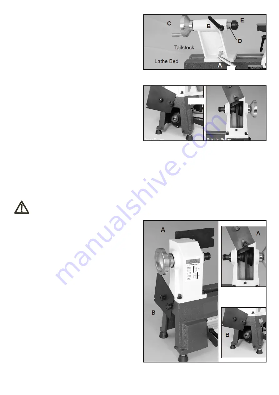
5.2 ADJUSTING THE TAILSTOCK
5.3 CHANGING SPINDLE SPEEDS
5.4 CHANGING THE DRIVE BELT
- Loosen the locking lever (A) to move the tailstock along
the lathe bed to the desired position for holding your
work piece. Then tighten the locking lever to secure the
tailstock on the bed. FIG. 5.2.
- To adjust the clamping action of the tailstock on the bed,
adjust the lower locking nut. See the instructions listed
FIG. 2.
- To adjust the tailstock spindle in or out to hold or release
your work piece, loosen the locking lever (B) and turn the
hand wheel (C). The tailstock spindle (ram) (D) will travel
from 0” to 1-3/4”. When the tailstock spindle holding the
live center (E) is in a desired position, tighten the locking
lever (A). FIG. 5.2
The lathe features five step motor and spindle pulleys to
provide different spindle speeds. Open the two access
covers to change spindle speeds. FIG. 5.3.
To change the belt, the whole spindle shaft needs to be
shifted right, out of the headstock, towards the tailstock.
This will allow the new belt to be slipped over the spindle
and onto the spindle pul-ley. Then the whole spindle shaft
assembly can be re-installed so turning can be resumed.
- Unplug the lathe from the power source.
- Remove any accessories from the spindle -spur center,
pen mandrel, chuck, faceplate, etc..
- Open the rear spindle pulley cover (FIG. 5.4,A) and the
lower, side motor pulley cover (B) to gain access to the
drive belt and pulleys that are inside of the headstock and
bed casting.
- Loosen the motor mount locking lever handle (FIG. 5.3,
F) and lift the motor mounting plate lever (G) to loosen the
tension on the belt. The belt can now be removed from
the lower motor pulley (FIG. 5.4, B).
- Loosen the set screws that attaches the hand wheel (C)
to the spindle, and remove the hand wheel. FIG. 5.5.
- Remove the set screw(s) that attaches the spindle pulley
to the spindle. The pulley should now be loose on the
spindle. FIG. 5.4 , A.
Fig.5.2
Fig.5.3
Fig.5.4
-11-
WARNING
Do not put excess tension on the drive belt or excess wear or damage to the bearing or motor
may result.
- With the access covers open, loosen the locking lever handle (F) that secures the motor in place, and raise the motor
mounting plate lever (G) to release the belt tension on the motor and spindle pulleys.
- Check the speed and belt position chart to determine the spindle speed required for your turning. Then move the drive
belt to the desired pulley combination.
- With the locking lever handle and motor being loose, the motor’s weight will provide the proper tension on the drive
belt. Re-tighten the locking lever and close access covers.


