Sawmill Alignment
Blade Installation And Alignment
Sawmill Alignment
HDSdoc091108
5-3
5
saw head.
2.
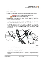
Start the engine (or motor).
3.
Pull lightly on the clutch handle, rotating the blade until the blade positions itself on the wheels.
WARNING!
Do not spin the blade wheels by hand. Spinning the
blade wheels by hand may result in serious injury.
4.
Release the clutch handle to stop the blade. Turn off the engine, remove the key and check the
position of the blade on the blade wheels.
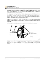
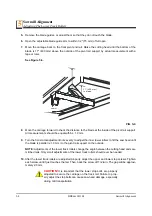
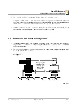
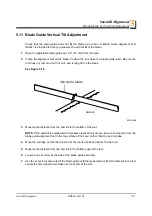
Check the vertical alignment of the idle-side blade wheel. The gullet of the blade should ride the
same distance from the front edge of the wheel at the top and bottom of the wheel. If it does not,
loosen and tighten the appropriate adjustment screws on the wheel shaft.
See Figure 5-2.
The blade wheels should be adjusted so that the gullet of 1 1/4" blades ride
3.0 mm (0.12") out from the front edge of the wheels (± 1.0 mm[0.04"]). The gullet of 1 1/2" blades
should ride 4.5 mm (0.18") from the front edge of the wheels (± 1 mm [0.04"]). Do not let the teeth
ride on the wheels.
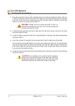
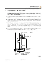
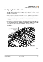
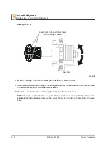
To adjust where the blade travels on the idle-side blade wheel, use the cant control shown in
Fig-
ure 5-1.
If the blade is too far forward on the wheels, turn the cant control counterclockwise. If it is too far
back on the wheels, turn the cant control clockwise.
Some adjustment in blade tension may be needed to compensate for adjustments made with the
cant control.
FIG. 5-2
SM0044D
1 1/2"
Blade
± 1 mm (0.04”)
1 1/4"
Blade
3.0 mm (0.12”)
± 1 mm (0.04”)
4.5 mm (0.18”)
Summary of Contents for LT40 DH
Page 1: ......
Page 2: ......
Page 69: ...Maintenance Carriage Track Wiper Scrapers Maintenance HDSdoc091108 3 5 3 FIG 3 3 ...


