


Safety
Use Proper Maintenance Procedures
1
1-6
HRdoc062321
Safety
Use Proper Maintenance Procedures
DANGER!
Make sure all electrical installation, service
and/or maintenance work is performed by a qualified
electrician and is in accordance with applicable electrical
codes.
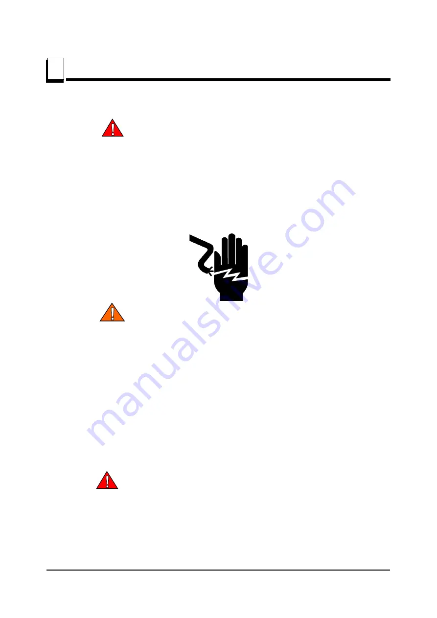
DANGER!
Hazardous voltage inside the electric boxes and
at the motor can cause shock, burns, or death. Disconnect
and lock out power supply before servicing! Keep all
electrical component covers closed and securely fastened
during resaw operation.
WARNING!
Consider all electrical circuits energized and
dangerous.
WARNING!
Disconnect and lock out power supply before
servicing the resaw! Failure to do so may result in serious
injury.
WARNING!
Never assume or take the word of another
person that the power is off; check it out and lock it out.
WARNING!
Do not wear rings, watches, or other jewelry
while working around an open electrical circuit.
WARNING!
Remove the blade before performing any
service to the motor or resaw. Failure to do so may result in
serious injury.
DANGER!
Never clean the blade or blade wheels using the
hend-held brush or scraper whilst the saw blade is in
motion.
CAUTION!
Before installation of the blade, inspect it for
damage and cracks. Use only properly sharpened blades.
Always handle the blade with extreme caution. Use suitable
carrier equipment for transporting the blades.