12
13
CONNECTIONS
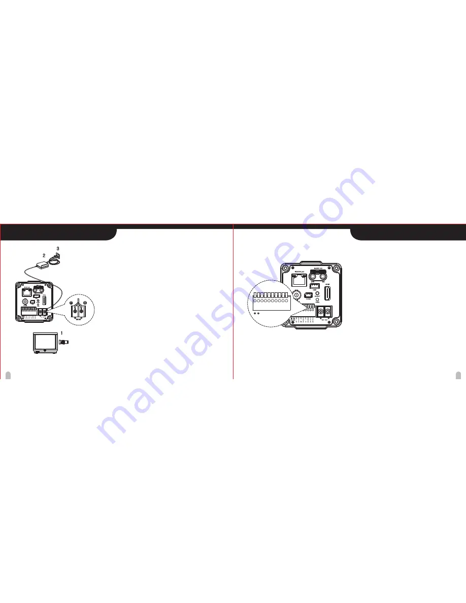
EXTERNAL DEVICE CONNECTIONS
Basic connection
The peripheral devices (DVR, monitor, lens, etc), DC adaptor
and cables are not supplied.
1. Connecting the monitor.
Make the video signal connection between the camera and the
monitor or DVR/NVR.
2. Use a commercially available DC12V adaptor.
Connect DC 12V power source to the DC 12V input terminal
or using 802.3af PoE power with network connection.
3. Insert the plug of this power cord into a wall outlet.
The POWER indicator will light. Adjust the picture on the monitor
using the Brightness and Contrast controls etc.
RS-485 COMMUNICATION
Connect to an external controller of RS-485 format.
(Protocol : Pelco-D 2400 supported)
Motion Detection Out
When the motion detection function is working.
DC3.3V is outputed to OUT pin and GND pin.
Day & Night input
Day/Night mode of the camera can be switched by
signal from an external device.
To use this function, <DAY&NIGHT> setting of the
camera should be set to the <EXT>.
Alarm IN
In order to make alarm on the web GUI, short or open
between D/I and GND port.
(Please refer the IP manual for more information)
Alarm OUT
Control the relay On/Off on the web GUI, relay will
short or open between DOA and DOB.
(Please refer the IP manual for more information)
Note : Use a relay unit if the voltage or current of the
connected device exceeds the ratings.
Connect video output(BNC / LAN) to the monitor or PC or NVR.
M
/
D
G
N
D
G
N
D
G
N
D
D
/
N
D
/
I
D
O
A
D
O
B
RS 485
2
3
1
DC12V


