LUMINOUS™ 570 SERIES LED LIGHT BAR - PAGE 4
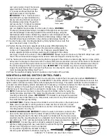
and nuts provided. Insert the tension
adjustment bolt through the strap’s
“L” bracket and thread bolt into the
light bar’s bracket, hand tighten.
IMPORTANT: The “L” bracket can be
repositioned for proper installation by
simply removing the bolt securing it to
the stainless-steel strap. Reposition
and secure the “L” bracket in preferred
location using the bolt, lock washer
and nut. Repeat the procedure for other side of vehicle. WARNING:
The two-(2) stainless-steel straps, included with the light bar are universal
and should always be securely installed to the window’s ledge, using the
hardware provided. Some vehicles may require a custom designed strap to
properly secure the light bar to the vehicle’s window ledge. Always make sure
that both straps have a full hold on the vehicles window ledge. See Fig. 10.
21. Secure the two slide mounting brackets by firmly tighten the four nuts that
were loosened in step 1. See Fig. 5.
22. Tighten the two-(2) tension adjustment bolts evenly. While tightening the
bolts, make sure the light bar remains in the desired mounting position
on the roof. Torque bolts to 10 to 12 ft.- lbs. Failure to properly tighten the
tension adjustment bolts and straps could result in damage to the vehicle
and injury or death to the driver or others. IMPORTANT: Always inspect to make sure that both straps have a full
hold on the vehicles window ledge and the tension bolts are torqued correctly. See Fig. 10.
23. The hooked end of the stainless-steel strap that is engaged to the vehicle’s window ledge has two holes, which
will secure the bracket to the vehicle with the sheet metal screws provided. Use each of the holes in the bracket
as a guide and drill the required holes to size 11/64” into the window ledge. Secure the stainless-steel strap to
the window ledge with the sheet metal screws. IMPORTANT: The installer may have to lower headliner and
inspect the selected location to ensure that there are no components, wires and or any other vehicle part that
could be damaged by drilling. See Fig. 11.
24. Place the weather-stripping back into position on both sides of the vehicle.
MOUNTING & WIRING SWITCH CONTROL PANEL
The light bar’s switch control panel needs to be mounted in a location that can easily be reached. WARNING: If
the vehicle is equipped with air bags, the installer MUST consult the vehicle’s shop or build manual to ensure that
light’s switch controller and wires will not affect deployment of air bags. This switch controller must be installed in
a location recommended by vehicle manufacturer. If necessary, consult manufacturer for their recommendation.
Failure to adhere to this warning could result in damage to the air bag and or reduce the
effectiveness of the air bag, which could result in bodily injury, or death to you or others.
25. NOTE: there are two methods to mount the switch controller, either by using the
double face tape provided or the metal mounting bracket, which is secured to the
mounting surface with screws. IMPORTANT: The installer must inspect the selected
location to ensure that there are no components, wires and or any other vehicle part
that could be damaged by drilling.
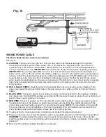
26. TAPE METHOD: Position the switch controller’s wire into the slots on the back panel.
Make sure the vehicle’s mounting surface is clean and free of dust, dirt, oil, wax
etc. Using the double face tape provided, secure the control panel to the selected
mounting location. See Fig. 12.
27. SCREW AND BRACKET METHOD: Position the switch controller’s cable into the
slots on the back panel so that the cable is flush with the back panel. Secure the
metal mounting bracket to the back of the switch controller with the four (4) screws
provided. Use the mounting bracket as a template, mark the two screw hole locations
and drill to size 11/16” and secure bracket with two (2) screws provided. See Fig. 13.
28. IMPORTANT: Connect the switch controller’s waterproof plug to the
light bars mating plug which was routed into the vehicle through the
access hole. The plugs can only be connected
in one position. Tighten the shoulder nut fully to
ensure a good waterproof connection. See Fig. 14.
Fig. 12
Fig.
13
Fig. 14
Can only connect in one
position. Match Notch
with Indent
Waterproof
Plug
Fig. 10
“L” Bracket
can be adjusted
to any holes on
Strap as needed
Tension
Adjustment Bolt
Strap
“L” Bracket
Strap
Tension Adjustment Bolt
Drill Hole Size
11/64"
Strap
Fig. 11
Shoulder
Nut

