


3
5. Reading and saving EDID from displays function.
6. With automatic EQ and amplification capabilities.
7. With signal recovery enhancements capabilities.
8. With on-site switching memory protection function.
9. Enhanced ESD electrostatic protection, special lightning protection circuit.
10. Allowing up to 8 channels HDMI audio video sources to be independently
switched to 8 HDMI Monitors, HDTV Displays, or Projectors.
11. The front panel LCD screen can display the switching status, input signal
characteristics and other information of each channel, which is clear and
intuitive.
12. Controllable by IR Remote, Front Panel Buttons, PC Software and RS232.
(IP and WIFI are Optional).
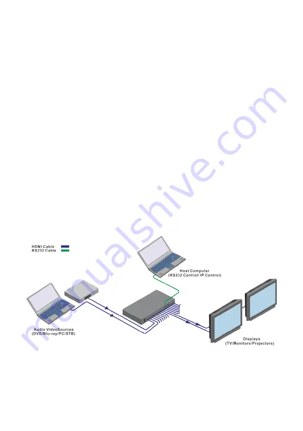
Connection and Operation
Matrix Connection
1.
Connect
HDMI
Sources
to
HDMX0808.
2.
Connect
HDMI
Sinks
to
HDMX0808.
3.
Power
On
all
the
Devices.
4.
Control
the
matrix
by
IR
Remote
Control,
Front
Panel
Buttons,
PC
Software
and
RS232.
(IP
and
WIFI
are
Optional).
Figure 2.
Matrix Connection Diagram


