background image

14

3062880_0910

Installation

The minimum system pressure is 1.0 bar.

The gas condensing boilers are approved exclusively for 

sealed unvented systems up to 6 bar. The maximum flow 

temperature is factory-set to 85 °C and may be adjusted 

to 90 °C if required. Generally, the flow temperature is 

80 °C for DHW operation.

There is no need for a minimum throughput at maximum 

flow temperatures below 85 °C.

Safety equipment

Information on scaling

Scaling can be strongly influenced particularly through 

the method of commissioning. Heat the system at the 

lowest output with an even and adequate throughput. For 

multi-boiler systems it is recommended to commission 

all boilers simultaneously to prevent the overall amount 

of lime concentrating on the heat exchanger surface of 

an individual boiler.

Note:

Provide a drain & fill valve at the lowest system point.

Before  commissioning,  all  hydraulic  pipes 

must undergo a tightness test:

Test pressure on heating water side max. 9 

bar.

Domestic hot water may be used as fill water and top-

up water.

Thoroughly flush the system prior to filling with water.

The use of chemical additives and softening using single-

stage ion exchangers is not permissible.

The  design  information  for  water  treatment 

must be observed, otherwise system damage 

due to water leaks may occur.

Wolf does not assume liability for any damage to the 

heat  exchanger  caused  by  oxygen  diffusion  in  the 

heating water. In the event of oxygen penetrating the 

system, we recommend a system separation through 

the interconnection of a heat exchanger.

In the case of systems with large volumes of water and 

those where large volumes of top-up water (e.g. through 

water losses) are required, observe the relevant local 

regulations regarding the prevention of damage in hot 

water heating systems through scaling and corrosion. 

Keep  a  system  log  (see  technical  information 

regarding  water  treatment  and  commissioning 

report).

Note: 

Check  with  Wolf  regarding  suitable  water  treatment 

measures. 

Heating water

Summary of Contents for MGK-130

Page 1: ... no 3062880_0910 Subject to technical modifications These installation instructions are to be retained by the user We cannot accept any warranty claims if these operating instructions have not been observed GB Wolf GmbH Postfach 1380 D 84048 Mainburg Tel 49 8751 74 0 Fax 49 8751 741600 Internet www wolf heiztechnik de ...

Page 2: ...e gas supply pressure 23 Commissioning Setting the BUS address 24 Displaying modifying control parameters 25 Limiting the maximum output 26 Changing the gas type CO2 settings 27 29 Testing the combustion parameters 30 Commissioning report 31 Technical information water treatment 32 System log 33 Engineering data 34 Function description System engineering 35 36 Technical information connection on t...

Page 3: ... switch is in the ON position This results in a risk of electrocution that may lead to injury or death The main supply terminals are live even when the ON OFF switch is in the OFF position NB indicates technical instructions that youmustobservetopreventmateriallosses and malfunctions on the boiler NB Safety instructions Fig Gas combination valve MGK 170 210 250 300 Danger from electrical voltage E...

Page 4: ...uide for gas installations in timber framed housing Important The appliance must be installed and serviced by a competent person as stated in the Gas Safety Installation and Use Regulations 1998 In IE the installation must be in accordance with the current edition of I S 813 Domestic Gas Installations the current Building Regulations and reference should be made to the current ECI rules for electr...

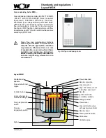
Page 5: ... which complies with the appropriate ventilation requirements Otherwise there is a risk of asphyxiation or poisoning Read these installation and maintenance instructions before installing the boiler Also take the technical engineering information into consideration Fig Wolf gas condensing boiler Flue outlet with test nipple Heat exchanger as a sectional design Flow connection Return connection Hig...

Page 6: ...8 Gas supply pressure Natural gas E LL mbar 20 20 20 20 20 LPG P mbar 50 50 50 50 50 Water capacity heating water heat exchanger l 12 15 4 16 20 22 Max permissible boiler pressure bar 6 6 6 6 6 Max permissible flow temperature C 90 90 90 90 90 Available gas fan draught Pa 10 200 10 150 10 150 10 150 10 150 Flue gas temperature 80 60 50 30 at Qmax C 65 45 65 45 65 45 65 45 65 45 Flue gas temperatur...

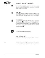
Page 7: ...re of 15 65 C The DHW temperature selector setting becomes ineffective when the system is combined with a digital room thermostat or a weather compensated controller The temperature will then be selected at the controller accessory 9 1 2 8 3 7 4 6 5 Heating water temperature selection Settings 2 8 correspond when factory set to a heating water temperature of 20 85 C The heating water thermostat se...
Page 8: ... run on period Summer mode Winter mode is disabled by rotating the heating water temperature selector into position In other words the boiler will then operate in summer mode Summer mode heating OFF means only DHW heating Frost protection for the heating system and pump anti seizing protection however remain enabled Thermometer The current heating flow temperature is displayed C 0 120 bar 0 4 2 1 ...

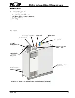
Page 9: ...ns 1 Operating instructions 4 Lifting slings Connections Flue outlet with integral test nipple Ø160 Ø200 Heating return Heating flow Gas connection Combustion air supply Ø160 Cable inlet 24V Power cable inlet 230 V Condensate drain connection Condensate drain connection optional Grommet Condensate hose Connection for balanced flue operation with ventilation air adaptor accessory ...

Page 10: ...ly humid conditions workshops laundry rooms hobby rooms etc This prevents the optimum burner function from being achieved The combustion air supplied to the boiler must be free from halogenated hydrocarbons e g as contained in sprays solvents cleaning fluids paints and adhesives Under the most unfavourable conditions these may lead to pitting of the boiler and even the flue gas system Never store ...

Page 11: ...feet spanner size 13 Fig Feet Fig Lifting eyes for lifting slings Lifting eyes for lifting slings Transportation into the installation room To ease the transportation into the boiler room lifting slings are supplied with the boiler Never use sack trucks NB Dimensions Fig Connection dimensions MGK 130 MGK 170 210 250 300 Fig Dimensions Total height incl connector MGK 130 250 1460 mm MGK 300 1510 mm...

Page 12: ...12 3062880_0910 Dismantling casing Dismantling the casing Fig Dismantling the front and side casing ...

Page 13: ...t not be able to be shut off Severely excessive boiler pressure due to excessive boiler water temperatures can burst the boiler body or the boiler pipework which would lead to a sudden escape of hot water risk of scalding Heating return Heating flow Fig Heating connections Provide system separation by means of a heat exchanger when using pipes which are not impermeable to oxygen This boiler is onl...

Page 14: ...must undergo a tightness test Test pressure on heating water side max 9 bar Domestic hot water may be used as fill water and top up water Thoroughly flush the system prior to filling with water Theuseofchemicaladditivesandsofteningusingsingle stage ion exchangers is not permissible The design information for water treatment must be observed otherwise system damage due to water leaks may occur Wolf...

Page 15: ... system accessory The neutralising system can be connected directly to the appliance Consumption approx 10 30 g kW p a Observe the associated instructions Trim the connection hoses so that the condensate can drain fully backup loops are prevented a perfect seal is ensured NB Fig Neutralising system accessory Condensate drain single boiler systems When installing the MGK as an individual appliance ...

Page 16: ...htness without the boiler Never release the test pressure via the gas valve Gas fittings on the appliance may be pressure tested to 150 mbar Higher pressure may damage the gas train resulting in a risk of explosion asphyxiation or poisoning Close the gas ball valve on the gas condensing boiler to pressure test the gas line Mount the gas ball valve in an easily accessible place Connection of a Wolf...

Page 17: ...NB With low outside temperatures the water vapour contained in the flue gas may condense and form ice on the flue Use on site measures to prevent ice from falling e g the installation of a snow catcher grille The boiler power supply terminals are live even when the ON OFF switch has been switched OFF General information electrical connection The installation must be carried out by a licensed elect...

Page 18: ...e appropriate cores at the Rast5 plug Leave the cores for the earth conductor gr ye approx 10 mm longer than those for L and N Push the inserts back into the terminal box casing Push the Rast5 plugs back into their correct positions Fig Junction box Fuse 5 A fast Rast5 plug Strain relief Terminal box The control regulating and safety equipment are fully wired and tested You only need to connect th...

Page 19: ... 15 A F1 1 2 1 2 1 2 L1 N L1 L1 N N L1 N L1 N Supply air damper with servomotor ußkasten 24VDC Limit switch NB Limit switch for supply air damper must be floating Otherwise the MGK control unit will be destroyed Note The contractor parameter input 1 factory setting for supply air damper and input 1 factory setting for supply air damper With the contact open the burner remains blocked for DHW and c...

Page 20: ...A1 is switched during cylinder heating 7 Ventilation damper Output A1 is switched first prior to each burner start The burner will however only be enabled after input E1 has been closed Important In any case input E1 must also be programmed as Ventilation damper The feedback to input E1 must be made with a floating contact Otherwise use an on site relay for potential separation 8 External ventilat...

Page 21: ... E1 must be closed within 12 seconds after the pump has been switched Where this is not the case the burner will be switched OFF and fault 41 will be displayed 5 Monitoring ventilation air damper factory setting E1 See parameters of output A1 no 7 ventilation damper The functions of input E1 can be scanned and adjusted with eBUS enabled Wolf control accessories The following functions can be alloc...

Page 22: ...ystem to 2 bar pressure In operation the pressure gauge must indicate between 1 5 and 5 5 bar Check the entire system for water leaks Remove the siphon Fill the siphon with water Refit the siphon Start the condensing boiler set the heating water selector to position 2 pump running illuminated status indicator ring constantly green Vent the heating circuit for this switch the gas condensing boiler ...

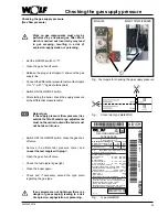
Page 23: ...ried out and the boiler must not be taken into use NB If any screws are not tightened there is a danger of gas escaping leading to a risk of explosion asphyxiation or poisoning Fig Test nipple for checking the gas supply pressure MGK 170 210 250 300 MGK 130 Gas Brennwert Heizgerät 1234567890 Herstellnummer Nennwärmebelastung Heizen Nennleistung Heizen 50 30 C Heizen 80 60 C Netzanschluß Q 28 160 k...

Page 24: ...n and the regular flame structure of the burner If the system water pressure falls below 1 5 bar top up with water until a pressure of 2 0 to max 5 5 bar has been achieved The illuminated ring shows a green colour if the boiler starts correctly Check the condensate drain Instructthecustomerintheoperationoftheboiler with the aid of the operating and installation instructions Complete the commission...

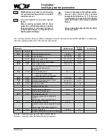
Page 25: ...w temperature hysteresis 1 to 20 K 8 K HG02 Lower fan speed 20 to 100 20 HG03 Higher fan speed DHW 20 to 100 100 GB04 HG04 Higher fan speed central heating 20 to 100 100 GB05 A09 Frost protection limit 10 to 10 C 2 C With connected outside temperature sensor and insufficient temperature pump ON GB06 HG06 Pump operating mode 0 to 1 0 0 Pump ON in winter mode 1 Pump ON with burner operation GB07 HG0...

Page 26: ... 100 MGK 170 Output kW 27 40 50 60 70 80 90 100 110 120 130 140 150 160 Display value 20 28 34 40 46 52 58 64 70 76 82 88 94 100 MGK 210 Output kW 34 40 55 70 85 100 115 130 145 160 175 190 200 Display value 20 23 30 37 45 52 59 66 73 81 88 95 100 MGK 250 Output kW 40 55 70 85 100 115 130 145 160 175 190 205 220 240 Display value 20 26 32 38 44 50 56 62 68 74 80 86 92 100 MGK 300 Output kW 45 62 7...

Page 27: ...for different gas types Turn anti clockwise Converting the MGK 130 to LPG P A separate conversion kit with gas restrictor gas combination valve and boiler coding card is required for this conversion Observe the information in the conversion instructions supplied Natural gas H Type Zero point adjusting screw MGK 130 1 turns Gas restrictor 1000 Conversion kits MGK LPG Type Part no conversion kit MGK...

Page 28: ...nsert the test probe of the CO2 test instrument into the flue gas test port Turn the temperature selector to Emissions test Illuminated status indicator ring flashes yellow Check the CO2 content at full load and compare the actual values with those in the table below Correct the CO2 setting as required using the gas throughput adjusting screw on the gas combination valve in accordance with the tab...

Page 29: ... is correct Take the following steps Check the standard settings of the zero point and throughput adjusting screws at the GCV and restrictor Repeat the adjusting process from section A The condensing boiler is correctly adjusted when the CO2 values correspond to those in the table below Appliance closed without casing at upper load Natural gas H 9 3 0 3 Appliance closed with casing at lower load N...

Page 30: ...he test port again Ensure the screws are seated firmly Return the temperature selector into its original position Testing the combustion air Hold the test probe into the combustion air supply and calibrate the tester or for balanced flue operation insert the test probe into the ventilation air adaptor Start the gas condensing boiler and turn the heating water temperature selector to the emissions ...

Page 31: ...d in acc with the technical information regarding water treatment 8 Boiler and system vented 9 System pressure 1 5 2 5 bar 10 Entered gas type and output onto label 11 Function test carried out 12 Flue gas test Gross flue gas temperature Inlet air temperature Net flue gas temperature Carbon dioxide content CO2 or oxygen content O2 Carbon monoxide content CO _____________ tA C _____________ tA C __...

Page 32: ...s greater than 20 l kW therefore Stage 3 must be selected Both fill and top up water must be within the range of 2 to 8 dH NB If the total hardness is too high some of the fill and top up water must be desalinated A desalinated water should be added Cmax Maximum permissible total hardness in dH CDHW Total hardness of the untreated DHW in dH We recommend allowing for the expected top up water durin...

Page 33: ... total hardness according to the table Proportion of desalinated DHW A A 100 Cmax 0 1 dH CDHW 0 1 dH x 100 Fill water to be treated Vtreatment l Vtreatment A x Vmax or Vtreatment A x Vsystem at stage 4 Commissioning Fill and top up water volumes Commissioning by Meter reading before first fill Zold in l Date Explanation Abbreviation Meter reading Znew in l Water volume V Znew Zold in l Total hardn...

Page 34: ...essure drop on the heating water side mbar Throughput m h Pump sizing MGK 130 170 210 250 300 The following Wilo and Grundfos pumps represent recommendations in conjunction with the installation of a MGK with a low loss header Select pumps in accordance with the respective system if no low loss header is to be installed MGK Type Version Connection type 130 Wilo Top S 25 7 and 30 7 230 V Rp1 Rp thr...

Page 35: ...on 1 Mixer circuit and cylinder heating with primary pump Configuration 2 Mixer circuit and convector heater circuit Configuration 3 Mixer circuit and heating circuit Configuration 8 Mixer circuit factory setting Configurations 4 7 9 13 See KM installation instructions Additional mixer heating circuits A maximum of 6 mixer modules and 1 cascade module can be combined in each system i e up to 7 mix...

Page 36: ...hould be connected to the eBUS Without the eBUS a BM Solar can be used Hydraulic For cascade systems we recommend the use of a low loss header Ensure the boiler circuit pump is carefully matched to the system If these have a higher pump rate than that required by the heating circuits warm flow water flows through the low loss header into the return thereby reducing the condensing effect In cascade...

Page 37: ... in line with demand Information on expansion vessel sizing can be found in the pricelist Aminimum pressure limiter 0 8 bar is integrated into the MGK If the majority of radiators are located below the appliance e g in the case of attic installations a low water indicator should also be employed The thermostatic DHW mixer pos 57 on the solar cylinder enables the draw off temperature to be reduced ...

Page 38: ...2651230 is required For type C the combustion air is drawn through a sealed system from the outside balanced flue combustion equipment Connection types Boiler type Gas boiler type 1 Category Germany Operating mode Can be connected to Open flue Balanced flue Moisture resistant chimney Room sealed balanced flue Room sealed balanced flue Building Regulation approved Flue Moisture resistant flue MGK B...

Page 39: ...concentric balanced flue for installation in a duct each balanced flue 160 225 15 m 15 m 13 m 8 m 3 m 200 300 15 m 15 m C33 Vertical flue for duct installation with horizontal concentric connection line length 2 5 m balanced flue 160 25 m 16 m 6 m 200 30 m 32 m 32 m 26 m 32 m C43 Connection to a moisture resistant balanced flue chimney balanced flue 160 2 Calculation 1 to EN 13384 1 200 3 C53 Term...

Page 40: ...on air adaptor for balanced flue operation Maintain the following clearance between the internal duct wall and the flue 30 mm for circular ducts 20 mm for square ducts Example open flue B 23 Install all horizontal ventilation air lines flues with approx 3 slope 5 cm m towards the appliance Any condensate must flow back to the appliance Example balanced flue C 53 Install all horizontal ventilation ...

Page 41: ...bend 2 m 1 x horizontal pipe 2 m Examples for MGK system layout 1 Gas condensing boiler with integral flue gas test nipple 2 Inspection bends 87 DN 160 3 Flue pipes DN 160 Length 500 1000 2000 4 Wall bezel 5 87 support bend DN 160 with support rail 6 Spacer 7 Ventilation air adaptor for balanced flue operation Maintain the following clearance between the internal duct wall and the flue 30 mm for c...

Page 42: ...Vertical roof outlet Ø 160 225 Mat no 2651346 Mat no 2651347 Mat no 2651350 Flat roof collar Ø 225 Mat no 2651458 Adaptor for balanced flue operation Mat no 2651332 Flue gas from the MGK Ventilation air to the MGK Engineering information combustion air flue gas routing ...

Page 43: ...43 3062880_0910 MGK façade C53 scheme Engineering information combustion air flue gas routing MGK concentric C33 scheme ...

Page 44: ...g themselves loose are excluded from our warranty if non CE approved third party equipment is used In addition to the boiler connection bend a maximum of two 90 diverters may be installed The duct must be free from contamination if the combustion air is drawn from it Connection to a combustion air and flue system type C63 that has not been tested together with the gas combustion equipment The unob...

Page 45: ...ssure switch X9 Boiler coding card X10 Earth terminal Y0 Gas combi valve Y0 gas combi valve gn ye B3 ionisation Burner E1 ignition unit M2 fan wh ye wh S5 gas pressure switch Network condensate pump black B2 return sensor wh wh ye ye S2 TW flue gas S4 flue gas pressure switch B1 flow sensor S3 water pressure switch S1 TW flow Fault message condensate pump grey Jumper X10 earth terminal Mains Outpu...

Page 46: ... L1 N L1 N L1 N L1 N rt rt B1 Vorlauf fühler S1 TW Vorlauf ws ge gn br S3 Wasser druck schalter P P 2 2 1 1 1 2 3 3 3 S5 Gasdruckwächter P 1 2 3 Junction box Power supply 230 V AC 50 Hz Z Heating circuit pump A1 Programmable output E1 Programmable input eBUS BUS connection for external control accessories AF Outside temperature sensor A1 Control PCB A2 LED PCB B1 Flow sensor B2 Return sensor B3 Io...

Page 47: ...side temperature sensor faulty The outside temperature sensor or cable is faulty Check lead Check the outside temperature sensor 16 Return sensor faulty The return temperature sensor or lead is faulty Check lead Replace the return sensor 20 Fault gas valve 1 A flame is detected for 15 s after burner operation even though gas valve 1 has received a shutdown command Replace the gas combination valve...

Page 48: ...24 5225 59 1289 94 406 10 27648 25 5000 60 1244 95 393 9 26189 26 4786 61 1200 96 382 8 24816 27 4582 62 1158 97 371 7 23523 28 4388 63 1117 98 360 6 22305 29 4204 64 1078 99 349 5 21157 30 4028 65 1041 100 339 4 20075 31 3860 66 1005 101 330 3 19054 32 3701 67 971 102 320 2 18091 33 3549 68 938 103 311 1 17183 34 3403 69 906 104 302 0 16325 35 3265 70 876 105 294 1 15515 36 3133 71 846 106 285 2 ...

Page 49: ...tor 7 Digital Wolf control accessories connection 21 Dimensions 11 Dismantling the casing 12 Drain valve 5 E Electrical connection general information 17 Emissions test mode 8 F Flow sensor 5 Flue gas inspector flue gas testing 30 Flue gas parameters 30 Flue gas pressure switch 5 Flue gas temperature switch 5 G Gas combination valve with gas pressure limiter 5 H Heating circuit pump connection 19 ...

Page 50: ...erview connections MGK 9 P Power supply 18 Pressure drop heating water 34 Pump sizing MGK 130 170 210 250 300 34 R Reset button 7 Return sensor 5 S Safety instructions 3 Saving energy 24 Scheme concentric C33 43 Scheme façade C53 43 Scheme vertical roof outlet balanced flue 42 Setting the BUS address for multiple heating appliances 24 Specification 6 Spread max 34 Standard settings for different g...

Page 51: ...agram 19 Ventilation air flue gas routing maximum length 39 Ventilation air flue gas routing overview 38 Ventilation air flue gas routing type of connections 38 Volume flow max 34 W Water pressure switch 5 Water treatment 32 Winter mode 8 Keyword index ...

Page 52: ...37 09 2009 DIN EN 483 06 2000 DIN EN 677 08 1998 In accordance with the following Directives 2009 142 EEC Gas Appliances Directive 92 42 EEC Efficiency Directive 2004 108 EC EMC Directive 2006 95 EC Low Voltage Directive This product is identified as follows Mainburg 16 11 2009 Gerdewan Jacobs Technical Management Klaus Grabmaier Product approval Wolf GmbH Postfach 1380 D 84048 Mainburg Tel 49 875...

Reviews: