


65
3061741_201712.indd
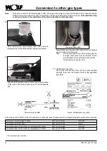
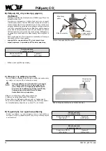
Conversion to LPG P (G31)
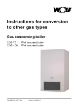
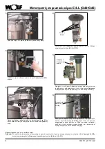
Remove the four SW8 screws at the gas connection fitting
and remove the fitting from the gas combination valve.
Remove the gas combination valve and gas restrictor.
Place the protective labels at the valve inlet and valve
outlet of the new gas combination valve at the apertures of
the removed valve. Return the removed gas combination
valve to Wolf.
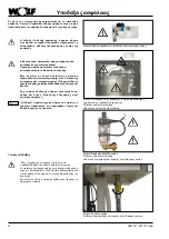
4)
Undo the gas combination valve from the mixing chamber
for gas/air (four SW8 screws).
4 x screws
SW8
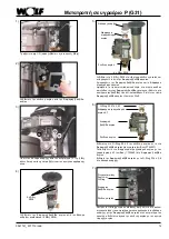
3)
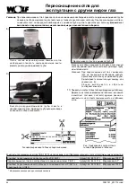
Undo the mixing chamber from the fan (three Allen screws
5 mm), and remove air inlet pipe where necessary
7)
6)
Push the O-ring, lubricated with silicone grease, into the
packing groove of the fan and fit the mixing chamber with
the gas combination valve to the burner fan.
Tighten gas connection fitting to gas supply line.
O-ring
Gas
combination valve
Gas connection
fitting
O-ring 23.47 x 2.62
Gas restrictor 6.7
Gas combinati-
on valve
Gas restrictor
5)
4 x SW8 screw
Gas connection
fitting
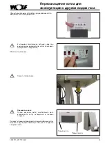
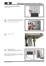
Unplug the connector
(first undo Phillips head
screws)
1)
Undo gas connection at the gas combination valve
2)
Mixing chamber
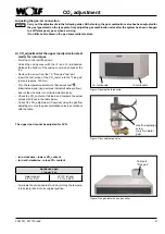
Use screws to secure the gas connection fitting with O-
ring 26 x 4 to the new LPG gas combination valve (part
no. 2744621).
Insert new 6.7 gas restrictor (part no. 1730640) into the
gas combination valve.
Use screws to secure the gas combination valve with O-ring
23.4 x 2.6 to the mixing chamber.
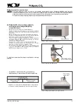
Threaded connection
Gas connection
Summary of Contents for CGB-100
Page 98: ...98 3061741_201712 indd ...
Page 99: ...99 3061741_201712 indd ...