16
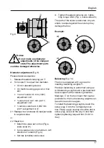
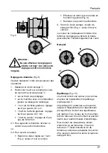
If outside turning holders
¿
(Fig. 5) are
mounted onto the serrated slides, the
threaded pin
¸
has to be removed before
use when using an inner coolant delivery
section.
Please note:
For dimensionally accurate cutting-edge
adjustment for outside turning we recom-
mend a cutting-edge adjustment correction
of a diameter of 1 mm (.039“).
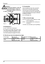
Insert holder for boring and outside tur-
ning without serrated slide (Fig. 6)
For fastening purposes, the clamping bolt
q
is mounted with a threaded taper pin
5
in the slider. The holder
w
is mounted onto
the K-profi le and fastened in place using a
cap screw
e
with washer.
Notice:
Do not fi t the serrated slides
without the coolant delivery
section. Always secure this
coupling section using the threaded
taper pin, as otherwise accidents may
occur due to loose pins.
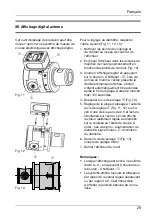
Outside tuning insert holders without
serrated slide Ø 4 – 58 mm (Ø .157“ –
2.283“)
(Fig. 7, 8)
When fastening the outside turning insert
holder without serrated slide, note the
installation position rotated through 180°.
When using this outside turning insert hol-
der, this rotated installation position means
that a diameter adjustment is required in the
manner opposite to the one described in
the „Diameter adjustment“ point (Page 17):
Turn in + = Diameter is reduced,
turn in – = Diameter increased.
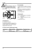
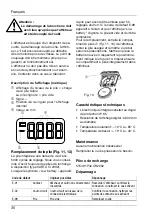
Clamping
(Fig. 9)
The slide is fastened in place using threa-
ded clamping pin
1
(tightening torque
3 Nm (26.55 in. lbs.)). This helps to prevent
infl uences such as machining or centrifugal
forces from changing the diameter. The
slider must be clamped during machining.
English
Fig. 5
Fig. 8
Fig. 7
¿
¸
Fig. 6
5
w
e
q
Summary of Contents for VARIOBORE 536
Page 1: ......


